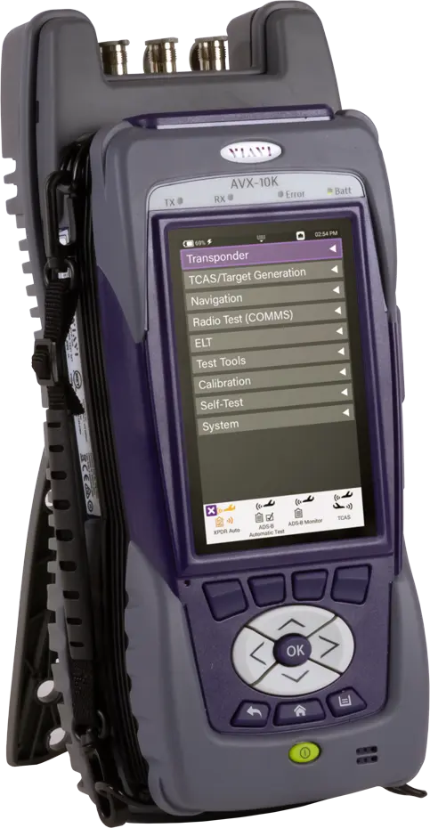
VIAVI AVX-10K Flight Line Test Set for Transponder, ADS-B, TCAS, NAV/COMM, DME and TACAN Testing
Handheld avionics flight line test set covering transponder, ADS-B, UAT, TCAS, NAV/COMM, DME/TACAN, ELT and VSWR/DTF testing in one device.
- Interrogation Frequency
- 1030 MHz
- RF Output Level, Antenna Port
- MTL + 6 dB typical, automatically controlled for a MTL range of -83 to -68 dBm
- RF Output Level Range, Antenna Port
- -67 to -2 dBm at antenna port
- Distance to UUT Antenna
- 6 to 200 ft with supplied antenna
Overview
The VIAVI AVX-10K is a flight line test set for avionics technicians. It covers performance verification of airborne communications, navigation and surveillance systems from a single device, ranging from quick automatic tests of an airborne system to in-depth troubleshooting with software-specific applications.
Testing can be carried out around the aircraft or in the cockpit, either from the unit's touchscreen display or from a mobile device. Test results and reports can be transferred via USB, Ethernet and wireless connections.
Mobile and remote operation
The VIAVI Mobile Tech app allows technicians to control the AVX-10K fully from inside the cockpit and provides access to manuals, quick cards, training videos and technical support. Smart Access Anywhere (SAA) provides secured remote access to the test set from laptops, tablets or smartphones, enabling real-time collaboration between maintenance and engineering teams.
Test coverage
Communications tests include AM, FM, SSB (HF) and SELCAL. Navigation tests include TACAN, DME, ILS (localizer, glideslope and marker beacon) and VOR. Surveillance tests cover military Modes 1, 2 and 3, Modes A, C and S, ADS-B Out, ADS-B In target generation at 1090 MHz and 978 MHz UAT, TCAS I/II and TAS, as well as ADS-B, GICB and UAT monitoring. Additional tools cover ELT beacons, VSWR, distance to fault and cable loss.
Key Features
- Quick airborne system auto-tests and in-depth troubleshooting from a single test set
- Touchscreen display with operation from a mobile device
- Full control from the cockpit via the VIAVI Mobile Tech app, with access to manuals, quick cards, training videos and technical support
- Secured remote access via Smart Access Anywhere (SAA) from laptops, tablets or smartphones
- Test reporting transferable via USB, Ethernet and wireless
- Communications testing: AM, FM, SSB (HF) and SELCAL
- Navigation testing: TACAN, DME, ILS (LOC, GS, MB) and VOR
- Transponder testing: Military Modes 1, 2 & 3 and Modes A, C, S
- ADS-B Out testing
- ADS-B In traffic target generation at 1090 MHz (ADS-B, ADS-R, TIS-B) and 978 MHz UAT (ADS-B, TIS-B, FIS-B)
- TCAS I/II and TAS testing
- ADS-B, GICB and UAT monitoring
- ELT, VSWR, distance to fault and cable loss testing
- ADS-B target generator with 5 targets referenced to a user-entered location or the built-in GPS receiver location
- Built-in GPS L1 C/A code receiver for UAT slot timing and ADS-B target reference position
- Software update via USB or StrataSync
Specifications
| Interrogation Frequency |
1030 MHz
Accuracy ±10 kHz
|
|---|---|
| RF Output Level, Antenna Port | MTL + 6 dB typical, automatically controlled for a MTL range of -83 to -68 dBm |
| RF Output Level Range, Antenna Port |
-67 to -2 dBm at antenna port
Resolution 0.5 dB; accuracy ±2 dB
|
| Distance to UUT Antenna | 6 to 200 ft with supplied antenna |
| RF Output Level Range, RF I/O Connector |
-115 to -47 dBm
Resolution 0.5 dB; accuracy -95 to -47 dBm (±1 dB), -115 to <-95 dBm (±2 dB)
|
| Mode S PRF | 50 Hz (±5 Hz) |
| ATCRBS PRF | 235 Hz (±5 Hz) |
| ERP (@ 1090 MHz) |
+45.5 to +59 dBm (35.5 to 800 watts)
Resolution 0.1 dB; accuracy ±2 dB
|
|---|---|
| Direct Connection Peak Pulse Power (@ 1090 MHz) |
+46.5 to +59 dBm (45 to 800 Watts)
Resolution 0.1 dB; accuracy ±1 dB
|
| Transmitter Frequency Range |
1087.000 to 1093.000 MHz
Resolution 10 kHz; accuracy ±50 kHz
|
| Receiver Sensitivity, Radiated MTL |
-79 to -67 dBm into 0 dBi antenna
Resolution 0.1 dB; accuracy ±2 dB, typical
|
| Receiver Sensitivity, Direct Connection MTL |
-79 to -67 dBm
Resolution 0.1 dB; accuracy ±2 dB
|
| Reply Delay, ATCRBS |
1.80 to 7.00 μs
Resolution 10 ns; accuracy ±50 ns
|
| Reply Delay, Mode S and ATCRBS Mode S ALL-CALL |
125.00 to 131.00 μs
Resolution 10 ns; accuracy ±50 ns
|
| Reply Delay Jitter, ATCRBS |
0.00 to 2.30 μs
Resolution 1 ns; accuracy ±20 ns
|
| DF 11 Squitter Period |
0.10 to 4.88 sec
Resolution 10 ms; accuracy ±10 ms
|
| Diversity Isolation |
0 to >20 dB (depending on test distance)
Test distance 1.83 m (6ft) to 28.96 m (95 ft); resolution 0.1 dB; accuracy ±3 dB
|
| Reply Frequency |
1090 MHz
Accuracy ±10 kHz
|
|---|---|
| Output Level Range, Antenna Port |
-67 to -2 dBm at antenna port
Resolution 0.5 dB; accuracy ±2 dB
|
| Distance to UUT Antenna | 6 to 300 ft. with supplied antenna |
| Reply Modes | TCAS I / II Mode C (with altitude reporting); TCAS II Mode S formats 0, 11, 16; E-TCAS Modes formats 0, 4, 5, 11, 16, 20, 21 |
| Range Delay |
0 to 260 nmi
Resolution 0.1 nmi; accuracy ±0.02 nmi
|
| Range Rate |
-1200 to +1200 kts
Resolution 10 kts; accuracy 10%
|
| Altitude Range |
-1000 to 126,000 ft.
Resolution 100 ft. (Mode C), 25 ft. (Mode S)
|
| Altitude Rate |
-10,000 to +10,000 fpm
Resolution 100 fpm; accuracy 10%
|
| ERP (@ 1030 MHz), ATCRBS and Mode S |
+43 to +58 dBm (20 to 631 watts)
Resolution 0.1 dB; accuracy ±2 dB
|
| Frequency Measurement Range |
1029.900 to 1030.100 MHz
Resolution 1 kHz; accuracy ±10 kHz
|
| TCAS Broadcast Interval |
1.0 to 12.0 sec
Resolution 0.1 sec; accuracy ±0.2 sec
|
| Transmit Frequency |
978 MHz
Accuracy ±10 kHz
|
|---|---|
| Output Level Range, Antenna Port |
-67 to -2 dBm at antenna port
Resolution 0.5 dB; accuracy ±2 dB
|
| Distance to UUT Antenna | 6 to 150 ft. with supplied antenna |
| Modulation Type |
BPFSK per RTCA DO-282B
Deviation ±312.5kHz typical
|
| ERP (@ 978 MHz) |
+35 to +57 dBm (3.16 to 500 watts)
Resolution 0.1 dB; accuracy ±2 dB
|
| Frequency Measurement Range |
977.96 to 978.04 MHz
Resolution 1 kHz; accuracy ±10 kHz
|
| RF Output Frequency, Single Mode | 10.0 MHz to 400.0 MHz in 100 kHz steps |
|---|---|
| Marker Beacon Channel | 72.0 MHz to 78.0 MHz in 25 kHz steps |
| VOR Channel | 108.0 MHz to 117.95 MHz in 50 kHz steps |
| LOC Channel | 108.1 MHz to 111.95 MHz in 50 kHz steps |
| G/S Channel | 329.15 MHz to 335.0 MHz in 50 kHz steps |
| Comm AM Channel |
10.0 MHz to 512.0 MHz in 25 kHz steps
8.33 kHz steps available 118.0 to 156.0 MHz; IFR4000 comparison data sheet lists 10.0000 MHz to 400.0000 MHz
|
| Comm FM Channel | 10.0 MHz to 512.0 MHz in 12.5 or 25 kHz steps |
| Comm SSB Variable | 10.0 MHz to 30.0 MHz in 100 Hz steps |
| Output Level, Antenna Port, Single Carrier (75 MHz to 512.0 MHz) |
+13 dBm to -67 dBm in 0.5 dB steps
Accuracy ±3 dB
|
| Output Level, RF I/O Port, Single Carrier (75 MHz to 512.0 MHz) |
-12 dBm to -130 dBm in 0.5 dB steps
Accuracy -12 dBm to -39.5 dBm (±2.5 dB), -40 dBm to -94.5 dBm (±2.0 dB), -95 dBm to -120 dBm (±3 dB)
|
| VOR Variable Bearing |
3600 digitally derived courses in 0.1° increments.
Accuracy ±0.1°
|
| LOC DDM Variable Range |
±0.4 in 0.001 DDM steps
Accuracy ±0.0025 DDM (±2.5 μA) ±3% of setting (≤+10 dBm Output Level)
|
| G/S DDM Variable Range |
±0.8 DDM in 0.001 DDM steps
Accuracy ±0.0048 DDM (±4.0 μA) ±3% of setting (≤+10 dBm Output Level)
|
| SELCAL |
32 ARINC 714A Tone Frequencies
SELCAL tones per DO-093A standard
|
| Reply Frequency Range |
962 to 1213 MHz
Accuracy ±10 kHz
|
|---|---|
| Output Level Range, Antenna Port |
-67 to -2 dBm at Antenna port
Resolution 0.1 dB; accuracy ±2 dB
|
| Range Delay, X and Y Channel |
0 to 450.00 nmi
Resolution 0.01 nmi; accuracy ±0.01 nmi
|
| Range Rate, X and Y Channel |
10 to 6500 kts
Resolution 1 kts; accuracy ±0.01 % typical, tested to ±0.5%
|
| UUT ERP |
+47 to +64 dBm
Resolution 0.1 dB; accuracy ±2 dB
|
| UUT Frequency Measurement Range |
1025.00 to 1150.00 MHz
Resolution 10 kHz; accuracy ±20 kHz
|
| Interrogation PRF |
1 to 300 Hz
Resolution 1 Hz; accuracy ±2 Hz
|
| Reply Frequency Range |
962 to 1213 MHz
Accuracy ±10 kHz
|
|---|---|
| Variable Channel Selection | 1 to 126 (X & Y) |
| Distance to UUT Antenna | 6 to 250 ft. with supplied antenna |
| Variable Range Delay, X and Y Channel |
0 to 450.00 nmi
Resolution 0.01 nmi; accuracy ±0.01 nmi
|
| Variable Range Rate, X and Y Channel |
0 to 6500 kts
Resolution 1 kts; accuracy ±0.01% typical, tested to ±0.5%
|
| 15/135 Hz Bearing Signal Modulation Levels |
15 Hz: 20% ±2.5%; 135 Hz: 20% ±2.5%
Distortion <2.5%
|
| Variable Bearing |
0 to 359.5° in 0.5° increments
Accuracy ±0.1°
|
| Power Meter (RF I/O Port) Frequency Range | 10.0 MHz to 512.0 MHz |
|---|---|
| Power Meter (RF I/O Port) Power Range |
0.1 to <1 W (resolution 0.01 W); 1 to <100 W (resolution 0.1 W); 100 to 1999 W (resolution 1 W)
External attenuator required for input power greater than 30W
|
| Power Meter (RF I/O Port) Accuracy |
±8% of reading ±1 count (100 to 400 MHz); ±12% of reading ±1 count (<100 MHz and >400 MHz) CW only
Accuracy specification excluding external attenuator
|
| Power Measurement (ANT Port) |
-35 to +30 dBm
10.0 MHz to 512.0 MHz; accuracy ±2.0 dB
|
| AM Meter Percent Modulation Range |
10 to 99%
Audio range 50 Hz to 3000 Hz; accuracy ±10% of reading
|
| FM Meter Deviation Range |
1 to 15 kHz
RF frequency range 136.0 to 512.0 MHz; accuracy ±(0.4 kHz + 8% of reading)
|
| ELT 121.5/243 Beacon Monitor Swept Audio Tone Range |
100 Hz to 3000 Hz
Accuracy ±10% of reading
|
| ELT 406 MHz Beacon Monitor Sensitivity | Antenna Port ≥-35 dBm; RF I/O Port ≥ 0 dBm |
| SWR Meter Frequency Range | 10.0 MHz to 1250.0 MHz |
|---|---|
| SWR Measurement Range |
1 to 7 for SWR
Accuracy SWR < 3:1 ±0.2 ±20% of reading; SWR ≥ 3:1 ±0.3 ±20% of reading
|
| Distance to Fault Measurement Range |
3 to 300 ft, 1 to 100 M
Accuracy ±1.5 ft + 1% of distance
|
| Cable Loss Measurement Range |
0 to -40 dB
10.0 MHz to 1250.0 MHz; accuracy ± (0.5 dB + 0.02 dB per dB of loss), typical, following calibration
|
| RF I/O Connector |
TNC, Input/Output
Impedance 50 Ω typical; VSWR <1.3:1
|
|---|---|
| RF I/O Maximum Input Level | 4 kW peak, 10 W average |
| Antenna Connector Maximum Input Level |
10 W peak, 0.5 W average
TNC; VSWR (30 to 1213MHz) <1.7:1
|
| SWR Port Maximum Input Level |
20 mW max, 0 VDC
TNC; VSWR <1.5:1
|
| Test Antenna Gain |
8 dB, Typical
VSWR <1.5:1
|
| Ethernet | Yes, x 2, remote control |
| USB | Yes, x2 |
| WiFi | Yes, 2.4 GHz and 5.0 GHz |
| Cloud | Yes, StrataSync data storage and software update |
| GPS |
Built in GPS L1 C/A code receiver
Used for UTC UAT slot timing and ADS-B target generator reference position
|
| Display |
Display graphical color 800 pixels x 480 pixels, 5” diagonal
Touch screen, daylight viewable, adjustable backlight, 4 softkeys
|
| Temperature Stability | ±1 ppm |
|---|---|
| Aging | ±1 ppm per year |
| Battery Type | Li Ion |
|---|---|
| Battery Duration | >4 hrs continuous operation, >8 hrs, Typical |
| Input Range (Test Set) | 11.5 VDC to 16 VDC |
| Power Consumption | <60 W Max |
| Input Range (Supplied External AC to DC Converter) | 100 to 250 V AC, 1.5 A Max, 47 to 63 Hz |
| Height | 12 in |
|---|---|
| Width | 5.3 in |
| Depth |
4 in
IFR6000/6015 comparison data sheet lists size 12 x 5.3 x 3.75 inches
|
| Weight (Test Set Only) |
<6.5 lbs
IFR6000/6015 comparison data sheet lists 7 lbs
|
| Operating Temperature |
-20°C to 45°C (-4° to 113°F) Continuous Use
≥45°C to 55°C (113° to 131°F) intermittent use, protected by automatic shutdown
|
|---|---|
| Storage Temperature | -30°C to 71°C (-22° to 159.8°F) |
| Battery Charging Temperature Range | 5°C to 40°C (controlled by internal charger) |
| Altitude | ≤4800 meters |
| Relative Humidity | 95% (±5%) from 5° to 30°C (41° to 86°F); 75% (±5%) from 30° to 40°C (86° to 104°F); 45% (±5%) from 40° to 55°C (104° to 131°F) |
| Environmental (Test Set) |
MIL-PRF-28800F, Class 2
Altitude, bench handling, drip-proof, humidity, shock, vibration, temperature and transit drop
|
|---|---|
| Blowing Dust | MIL-STD-810F, Method 510.4, Procedure 1 |
| Explosive Atmosphere | MIL-STD-810F Method 511.4, Procedure 1 |
| Safety Compliance | UL-61010B-1, EN 61010-1, CSA 22.2 No 61010-1 |
| EMC | EN 61326 |
Specifications are taken from the manufacturer's documentation. See the datasheet for complete and current values.
Applications
- Flight line avionics maintenance
- Transponder and ADS-B compliance testing
- TCAS and TAS testing
- NAV/COMM radio testing
- DME and TACAN testing
- ELT beacon testing
- Antenna and cable VSWR, distance-to-fault and cable loss testing
- Commercial aircraft maintenance
- Military avionics maintenance
- MRO operations
Included
- Test antenna (supplied antenna)
- External AC to DC converter
Documents & Resources
Related Products
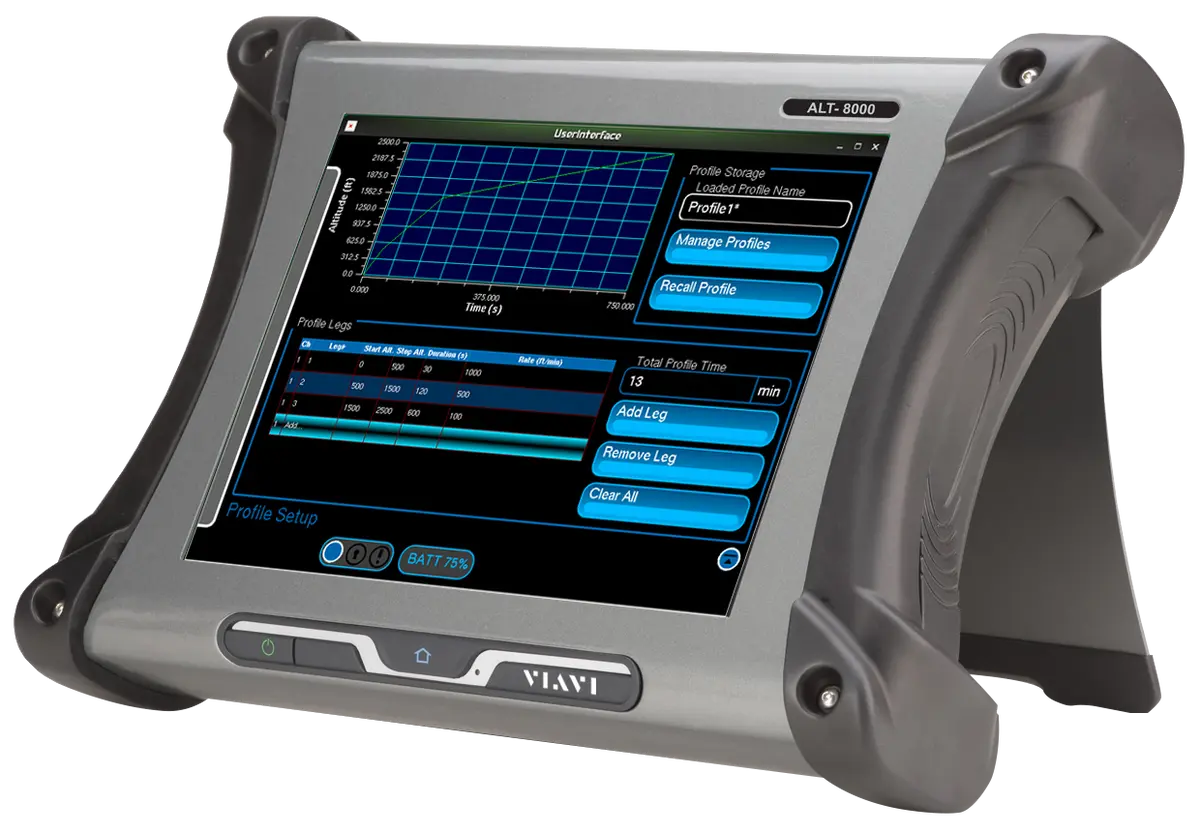
Portable RF-based flight line test set for installed 4.3 GHz FMCW and pulse radio altimeters, with a 12-inch color touch-screen.
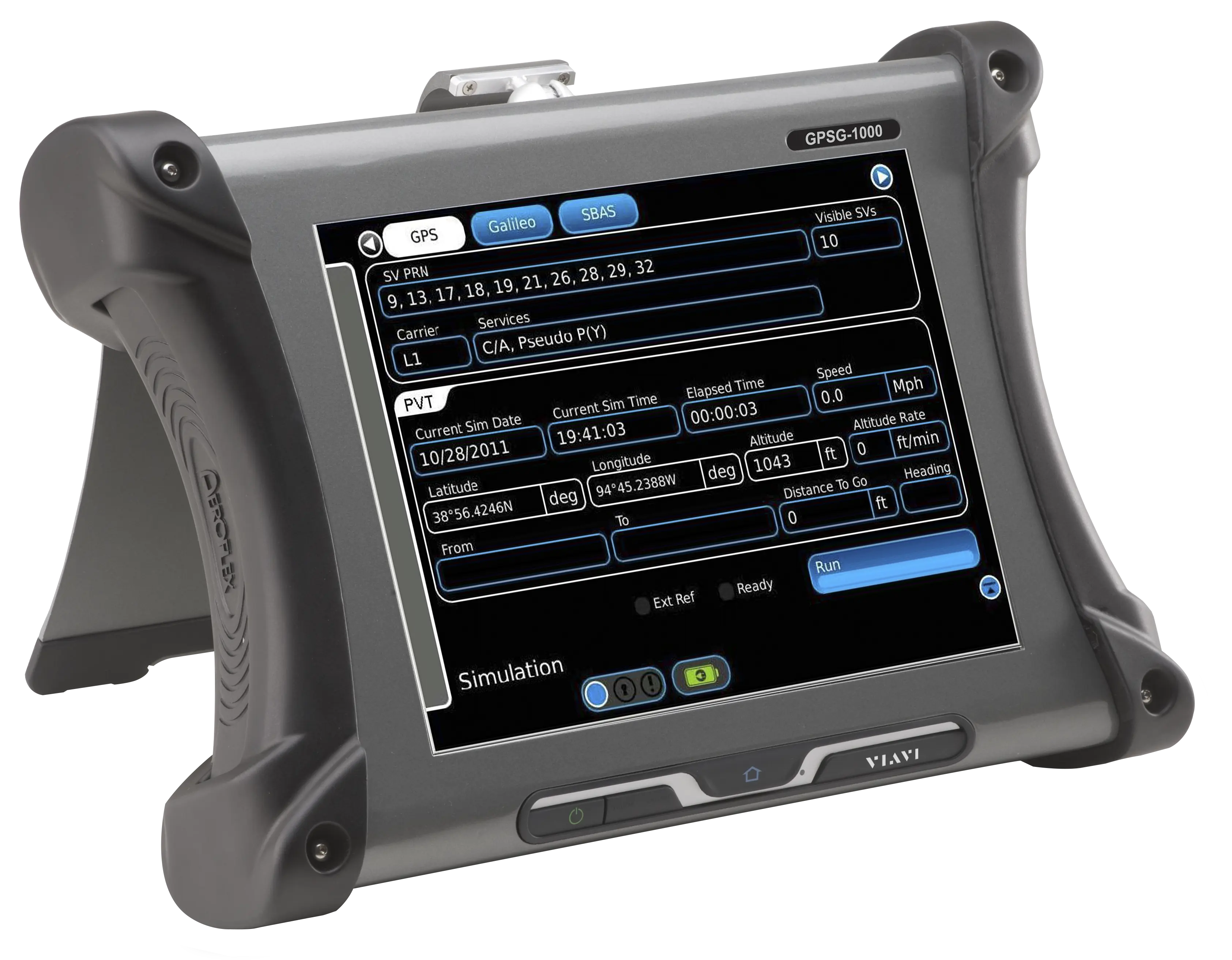
Portable 12-channel GPS and Galileo positional simulator with WAAS/EGNOS SBAS simulation for testing GPS-enabled receivers.
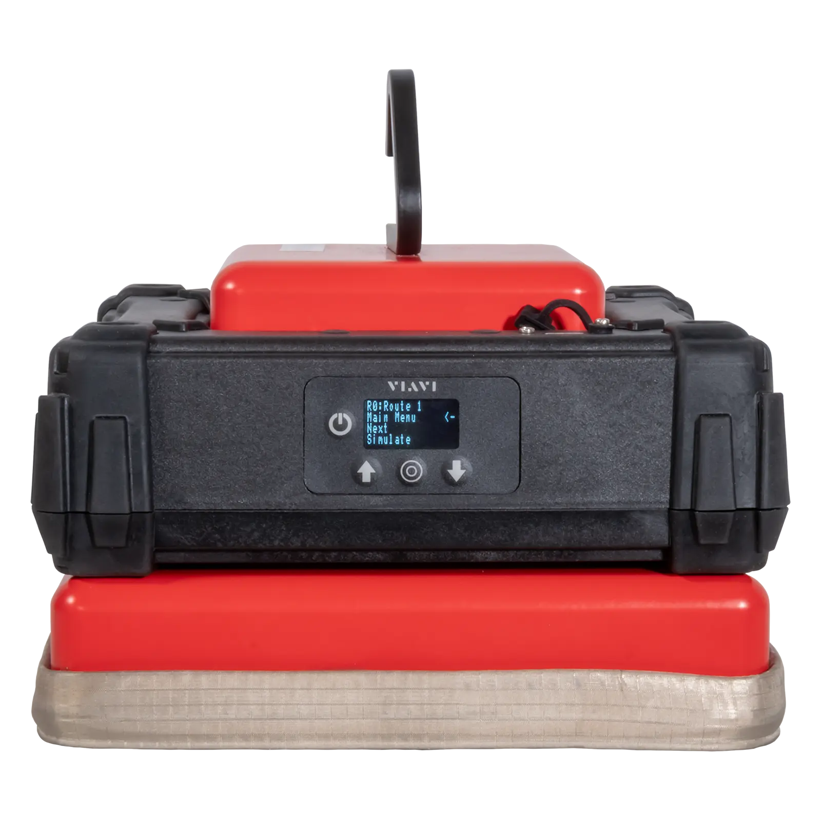
Portable L1 GPS position simulator that provides static waypoints and dynamic routes for avionics testing and GPS receiver verification.
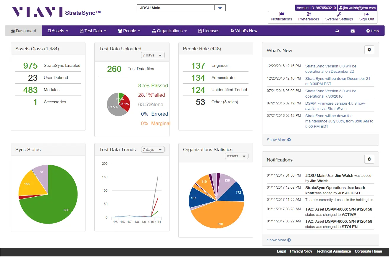
Hosted, cloud-based asset, configuration and test data management for VIAVI instruments, keeping software and options up to date.
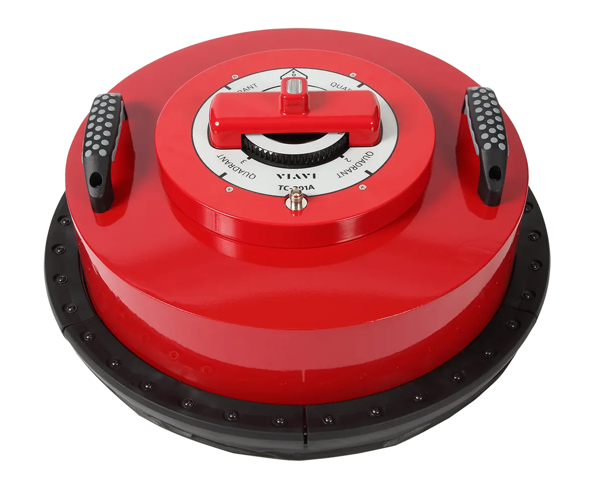
Combined TCAS and transponder directional antenna couplers that shield the RF signal during avionics flight line testing.