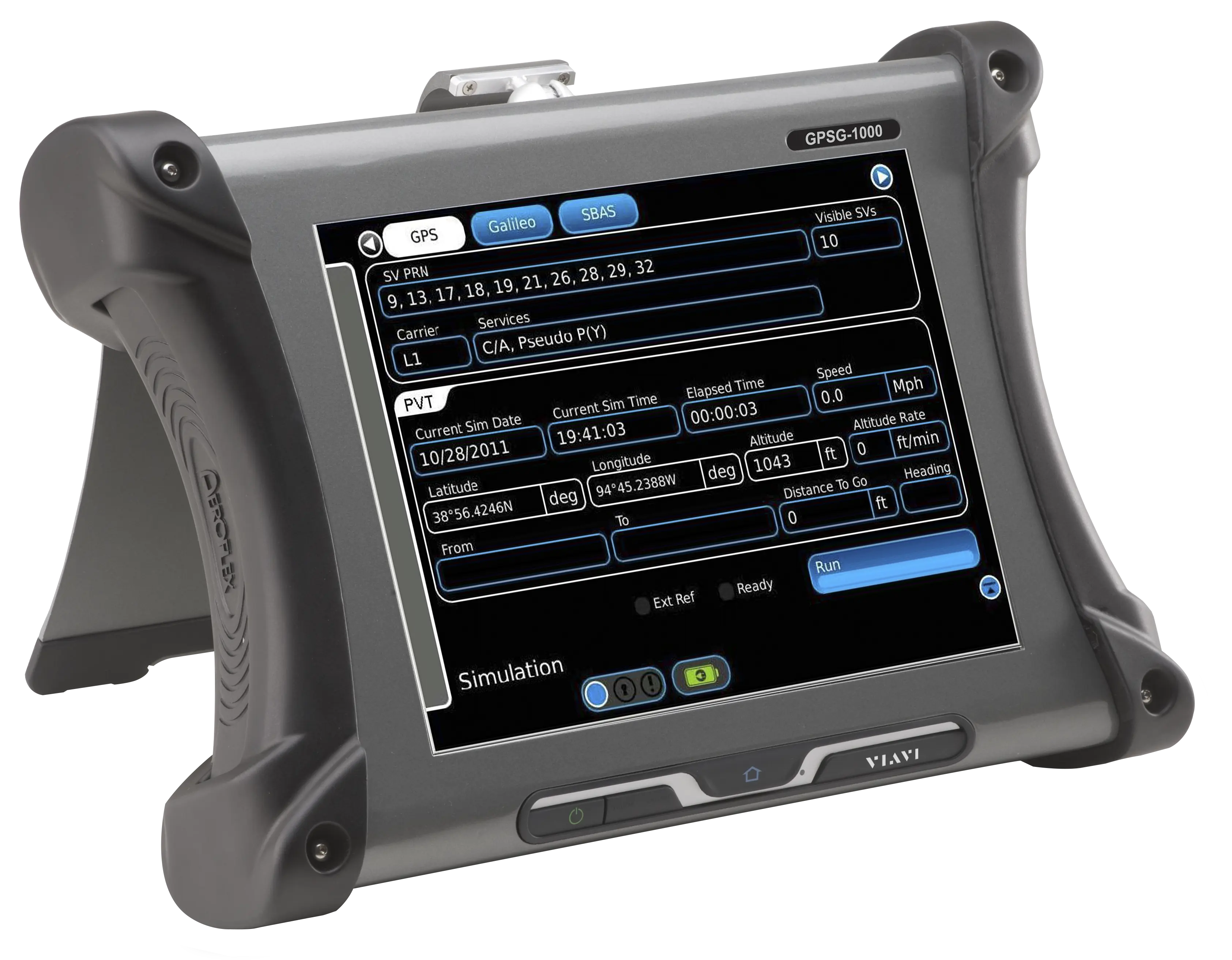
VIAVI GPSG-1000 GPS/Galileo Portable Positional Satellite Simulator
Portable 12-channel GPS and Galileo positional simulator with WAAS/EGNOS SBAS simulation for testing GPS-enabled receivers.
- Display
- 12” color LCD, sunlight readable with back light
- Controls
- Touch screen
Overview
The VIAVI GPSG-1000 is a portable, configurable GPS and Galileo positional simulator. It is a 12-channel test set that creates three-dimensional simulations for testing GPS/Galileo receivers, including WAAS/EGNOS SBAS simulation, and is designed to be software upgradable.
System
The simulated 3D position can be entered by the user in latitude/longitude/height format, or simulated dynamically using a multi-leg waypoint entry scheme. An unlimited number of navigation plans can be saved and recalled under a user-assigned name. A built-in GPS receiver allows positional simulation in the form of a range, heading and altitude based on the current test set position.
Satellite Vehicle Selection and SBAS
All GPSG-1000 configurations allow GPS and Galileo satellites to be mixed, and the Galileo codes can be updated via a text file upload. SBAS satellites (WAAS/EGNOS) can be selected manually or automatically based on the simulated position.
Waypoints
Waypoint legs join in 3D space, with either range rate or altitude rate calculated automatically. Trajectory changes are calculated to simulate real-world navigation: heading changes between legs use realistic rates of turn, and altitude changes use realistic rates of climb or descent. Waypoints can be entered in latitude/longitude form or recalled from an airport or city database.
Setup
A setup page lets the user set system, user and RF connection parameters.
Key Features
- GPS signals simulated: L1, L1C, L2C, L5 (some receivers require synchronized L1 transmissions to track L1C, L2C or L5)
- Galileo signals simulated: E1, E5, E5a, E5b (some receivers require synchronized E1 transmissions to track E5 signals)
- Simultaneous GPS/Galileo simulation
- WAAS/EGNOS SBAS simulation
- Static and dynamic simulations via NMEA-0183 file record and playback
- 12 channel configuration available with upgrade path (RAIM supported)
- Programmable space vehicle (SV) parametrics and health
- User or built-in GPS receiver referenced time and date
- PVT data available via RS-232
- User defined data transferable between linked GPSG units
- Ethernet remote control interface
- Galileo codes updatable via text file upload
- Unlimited navigation plans saved and recalled by name
- Waypoints recalled from an airport or city database
Specifications
| Display | 12” color LCD, sunlight readable with back light |
|---|---|
| Controls | Touch screen |
| Coupler Type | Cavity, patch |
|---|---|
| Coupling Loss | 21.5 dB typical at 1575.42 MHz |
| Isolation |
>25 dB at 1575.42 MHz
The separate GPSG Antenna Coupler data sheet states >20 dB isolation
|
| Dimensions |
7.54 x 7.46 x 7.46 in (19.15 x 18.95 x 18.95 cm)
Maximum antenna height accommodated 1.5 in
|
| RF Gasket | Flexible seal |
| Connector | TNC |
| Positioning | By hand or with optional 8 ft placement pole via hook. |
| Placement Security | Weighted peripheral bag |
| Multiple GPS Antenna Support | Supports two to three GPS antennas using optional antenna coupler kits. |
| Impedance | 50 Ω |
|---|---|
| SWR | 1.3:1 maximum |
| Connector | TNC x 2 |
| Coupling | AC (maximum DC input 50 V) |
| L1 | 1575.42 MHz (C/A, pseuo P(Y), SBAS) |
|---|---|
| L1C | 1575.42 MHz |
| L2 | 1227.60 MHz (pseudo P(Y)) |
| L2C | 1227.60 MHz |
| L5 | 1176.45 MHz (New Civil SoL) |
| E1 | 1575.42 MHz (pseudo-PRS, [pseudo-G/NAV]), (OS, CS, SoL, [I/ NAV]) |
|---|---|
| E5 | 1191.795 MHz center frequency |
| E5a | 1176.45 MHz (OS, (F/NAV)) |
| E5b | 1207.14 MHz (CS, SoL, (I/NAV)) |
| Accuracy | Same as master oscillator |
|---|---|
| Inter Channel Bias | Zero (digital design) |
| Frame Sync Output | LVTTL |
| Channels | 1-12 SV simulation, selectable |
| GPS PRN | 1 to 32 |
| Galileo PRN | 1 to 36 |
| SBAS PRN | 120 to 138 |
| Static Positional Simulation | Via user entry of Latitude/Longitude/Altitude or selectable from waypoint database |
| Dynamic Positional Simulation | Create, store, and recall routes consisting of multiple route points. |
| Trajectory Simulation | Record and playback GPS receiver data. |
| Almanac | Obtainable from built-in GPS receiver or external file load in .alm format |
| NAV Data | Navigation data is computed in real-time to match the simulation. |
| Doppler Error (selectable frequency offset) | ±5.0 kHz, 1 Hz increment |
|---|---|
| Amplitude Offset |
±15 dB in 1 dB increments
Sets SV carrier amplitude offset from main attenuator setting
|
| Step Error |
±10 km in 1 m increments
Sets SV pseudo range error; used for RAIM testing
|
| Satellite Health | Allows selection of GOOD or BAD |
| Code Carrier Coherence Range |
2 m/S
Sets frequency variation between code carriers
|
| Code Carrier Coherence Increment | 1 mm/S |
| L1 C/A Code Rate |
1.023 Mc/s
Primary sequence length 1023 bits; BPSK; 50 sps
|
|---|---|
| SBAS | WAAS/EGNOS L1, L5 |
| L2C Code Rate |
0.5115 Mc/s
Sequence length 10230/767250 bits; BPSK; 50 sps
|
| L1 P(Y) (not encrypted) |
Long random codes simulated
Code rate 10.230 Mc/s; sequence length 15345000 bits; BPSK
|
| L1C Code Rate |
10.230 Mc/s
Sequence length 10230 bits; BOC (1, 1)
|
| L5 Code Rate |
10.230 Mc/s
Sequence length 10230 bits; QPSK
|
| E1 PRS | not supported |
|---|---|
| Pseudo G/NAV |
Long random codes simulated
Code rate 2.5575 Mc/s; sequence length 25575 bits; 100 sps; Interplex/CBOC; sub-modulation BOC (15, 2.5)
|
| E1 OS | Complete implementation (I/NAV) |
| E1 CS | Null message content (pseudo I/NAV) |
| E1 SoL | Compliant, no integrity alerts (I/NAV) |
| E1 Code Rate |
1.023 Mc/s
Sequence length 4092 (primary) x 1 (secondary) bits; 250 sps; Interplex/CBOC; sub-modulation CBOC(6,1,1)
|
| E5a OS | Complete implementation (F/NAV) |
| E5a Code Rate |
10.23 Mc/s
Sequence length 10230 (primary) x 20 (secondary) bits; 50 sps; ALTBOC
|
| E5b OS | Complete implementation (F/NAV) |
| E5b CS | Null message content (pseudo I/NAV) |
| E5b SoL | Compliant, no integrity alerts (I/NAV) |
| E5b Code Rate |
10.23 Mc/s
Sequence length 10230 (primary) x 4 (secondary) bits; 250 sps; ALTBOC
|
| Max Relative Velocity | ±1000 Kts (514 m/s) |
|---|---|
| Max Relative Acceleration | ±98 m/s2 |
| Max Relative Jerk | ±20 m/s3 |
| Max Altitude | 100,000 ft. |
| Error Models | Atmospheric |
| Pseudorange Accuracy | <0.1 m |
| Pseudorange Rate Accuracy |
±0.01 m/s (RMS)
With respect to master oscillator
|
| RF Output Level, Direct | -93 to -155 in 1 dB step |
|---|---|
| RF Output Level, ANT Coupler | -68 to -130 in 1 dB step |
| RF Output Accuracy |
±2 dB accuracy into 50 Ω (AC coupled)
Standard cable, 4 dB loss
|
| Spurious | <-35 dBc over the bandwidth (40 MHz) |
| Harmonics | <-45 dBc |
| Frequency | 10 MHz nominal |
|---|---|
| Temperature Stability | ±0.05 ppm |
| Aging Rate | ±0.3 ppm /yr., ±2.5 ppm /10 yr. |
| Uncertainty | ±1 ppm |
| External Reference Input Level | 0.25 to 6.0 Vp-p |
| External Reference Input Impedance | 50 ohm nominal |
| External Reference Input Frequency | 10.0 MHz ±10 Hz |
| External Reference Output Level | 1.5 Vp-p nominal into 50 Ω |
| External Reference Output Frequency | 10.0 MHz nominal |
| PVT Data | RS-232 |
|---|---|
| Remote Control Interface | Ethernet |
| Battery | 14.4V 6.75 Ah Lithium Ion |
|---|---|
| Battery Temperature Range for Charging | 0° to 45°C (32° to 113°F) |
| DC Input | 11-32 VDC 75 W max. 5 A max. |
| Operational Temperature |
-20° to 55° C (-4° to 131°F)
Test set
|
|---|---|
| Storage Temperature |
-30° to 71° C (-22° to 159.8°F)
Test set
|
| Operational Humidity | MIL-PRF-28800F Class 2 |
| Storage Humidity | MIL-PRF-28800F Class 2 |
| Altitude | 10,000 feet |
| AC to DC Converter Use |
Indoors
Supplied external AC to DC converter
|
| AC to DC Converter Operating Temperature | 5°C to 40°C (41° to 104°F) |
| AC to DC Converter Storage Temperature | -20°C to 71°C (-4° to 159.8°F) |
| Dimensions (H x W x D) |
11.22 x 15.15 x 3.54 in (28.5 x 38.5 x 9 cm)
Web page lists 10.6”H x 13.9”W x 3.4”D (27.0 cm x 35.5 cm x 8.7 cm); data sheet value used
|
|---|---|
| Dimensions (Shipping Case) | 20.8 x 31.5 x 13 in (53 x 80 x 33 cm) |
| Weight, Test Set |
15.5 lb (7 kg)
Test set only
|
| Weight, Kit |
52 lb (23.5 kg)
Kit with shipping case
|
| Vibration, Shock, Transit Drop, Drip Proof, Dust, Explosive Atmosphere |
MIL-PRF-28800F Class 2
Test set
|
|---|---|
| Safety Compliance |
UL-61010-1, EN-61010-1, WEEE, ROHS
Test set
|
| EMC Emissions | MIL-PRF-28800F Class 2, EN 61326-1 Class A, EN 61000-3-2, EN 61000-3-3 |
| EMC Immunity | MIL-PRF-28800F Class 2, EN 61326-1 Class A |
| AC-DC Converter Safety Compliance | UL 1950 DS, CSA 22.2 No. 234, VDE EN 60 950 |
| AC-DC Converter EMI/RFI Compliance | FCC Docket 20780 Curve “B” |
| AC-DC Converter EMC | EN 61326 |
| Transit Case Drop Test | FED-STD-101C, Method 5007.1 Paragraph 6.3, Procedure A, Level A |
| Transit Case Falling Dart Impact | ATA 300 Category I |
| Transit Case Vibration, Loose Cargo | FED-STD-101C Method 5019 |
| Transit Case Vibration, Sweep | ATA 300 Category I |
| Transit Case Simulated Rainfall | MIL-STD-810F Method 506.4 Procedure II of 4.1.2; FED-STD-101C Method 5009.1 Sec 6.7.1 |
| Transit Case Immersion | MIL-STD-810F Method 512.4 |
Specifications are taken from the manufacturer's documentation. See the datasheet for complete and current values.
Applications
- General testing of civil GPS and Galileo receivers
- Testing of non-encrypted military GPS receivers
- Positive Train Control
- Asset tracking and telematics
- TAWS / WAAS / GBAS
Included
- Supplied external AC to DC converter
- Shipping case
Options & Accessories
| Option | Description |
|---|---|
| 87636 | GPS Antenna coupler — Provides >20 dB isolation and shielding from outside GPS signals; L1/L2/L5; TNC female; fits GPS antennas smaller than 6.5” x 6.5” x 1.5” |
| 90106 | Kit, Antenna Coupler Pole, 8 ft. w/ D Ring |
| 88753 | Weighted Bag |
| 112830 | Cable Coax, TNC-TNC 6’ |
| 114131 | Cable Coax, TNC-TNC 25’ |
Documents & Resources
Related Products
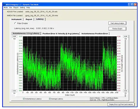
PC software for dynamic performance testing of ADS-B Out equipment against AC 20-165B, with compliance reports and system latency analysis.
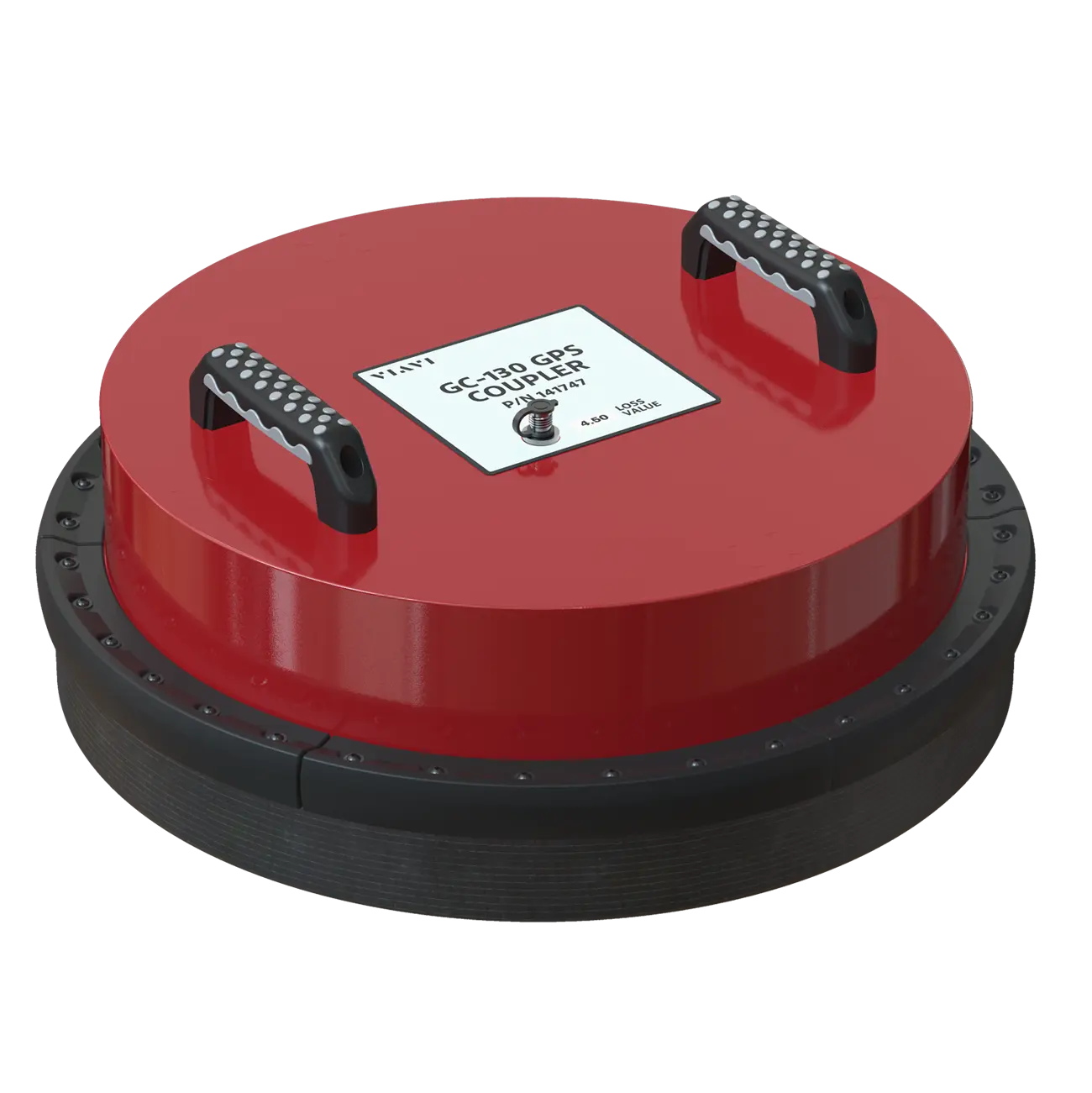
GPS antenna coupler kit that gives more than 20 dB of antenna isolation for GPS simulation in hangars and other areas with poor GPS coverage.