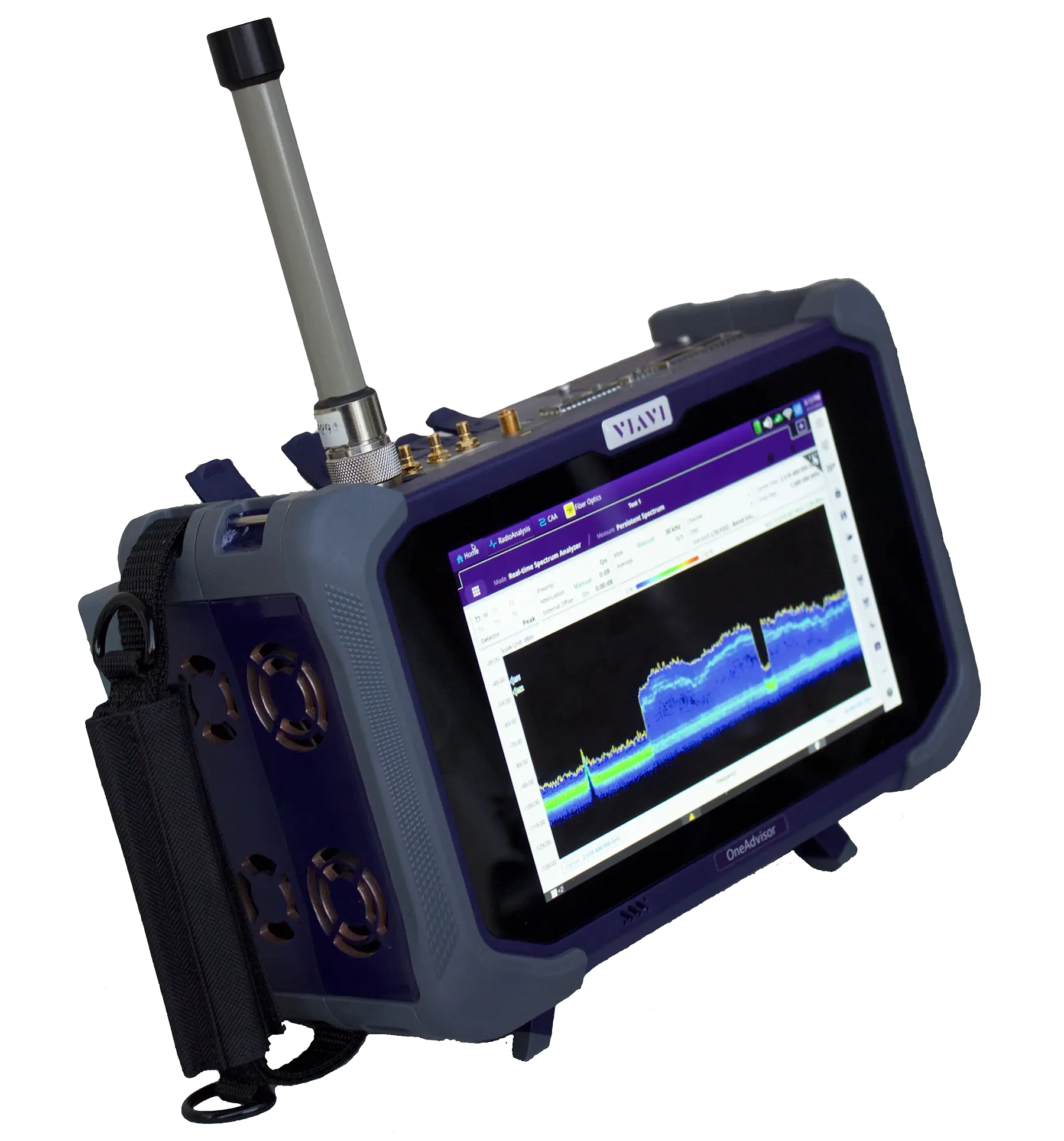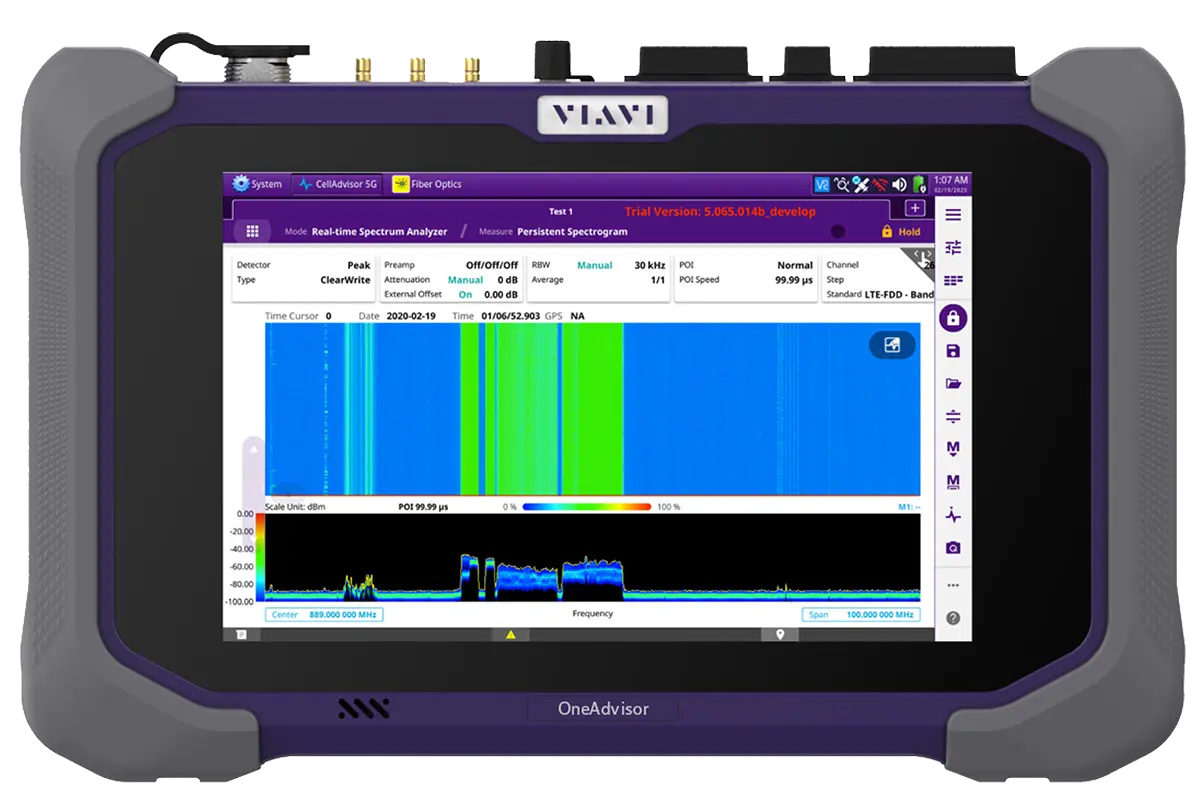
Radio Analysis Module SPA06MA 9 kHz to 6 GHz Spectrum and Signal Analysis Module for OneAdvisor 800
6 GHz radio analysis module for the VIAVI OneAdvisor 800 covering spectrum, interference, 4G LTE and 5G NR signal analysis in the field.
- Frequency range
- 9 kHz to 6 GHz
- Frequency reference stability
- ±0.5 ppm (-30 to 85°C) + aging
- Frequency reference accuracy with GPS
- ±25 ppb
- GPS holdover
- ±50 ppb
Overview
The SPA06MA is a member of the VIAVI Radio Analysis Module (SPAxxMA) family that pairs with the OneAdvisor 800 field test platform. It covers 9 kHz to 6 GHz and turns the OneAdvisor 800 into a portable test set for RF characterization, cellular technologies (4G and 5G), fiber links and Ethernet networks, with test capabilities that include spectrum analysis, signal analysis, RFoCPRI interference analysis, Ethernet and O-DU emulation.
The spectrum analyzer provides sweep-tuned, FFT and gated-sweep measurement modes, with a preamplifier, six traces and six markers. Optional real-time spectrum analysis adds up to 100 MHz of instantaneous bandwidth with persistence spectrum and spectrogram displays. Further software options add an interference analyzer with up to 72 hours of recording, TDD Auto Gated Spectrum (TAGS) for 5G NR, route mapping, EMF measurement and channel scanning.
Cellular signal analysis
Over-the-air and signal-analysis options are available for LTE/LTE-A FDD and TDD, 5G NR FR1 (410 MHz to 6 GHz), DSS, NSA and GSM/GPRS/EDGE. These include channel power, ACLR, carrier and beam scanners, control channel and EVM measurements, synchronization analysis and route maps, as well as a blind scanner for identifying LTE, NR and DSS carriers.
Transport and fronthaul
The datasheet also describes RFoCPRI interference analysis for CPRI rates 1 to 8, Ethernet testing from 10M to 100GE with RFC 2544 and Y.1564 workflows, IEEE 1588v2 PTP, IPv6, packet capture with on-instrument Wireshark decode, and CPRI BERT. The SFP+ and QSFP cages are listed for the SPA06MA-O variant only; the SPA06MA is specified for more than 3 hours of battery operation in spectrum mode.
Key Features
- Frequency coverage from 9 kHz to 6 GHz
- Real-time persistent spectrum analysis with up to 100 MHz of instantaneous bandwidth
- 4G-LTE and 5G-NR compliance, including blind-scanner, signal coverage, and synchronization assessment
- Ethernet verification for 1G, 10G, 25G, and 100G
- Open RAN capable, validating Open Radio Units (O-RU) with O-DU emulation
- Fiber characterization supporting OTDR (CWDM, DWDM) and multi-channel verification
- Versatile all-in-one portable field test solution on the OneAdvisor 800 platform
- Multi-functional test solution for RF characterization, cellular technologies (4G and 5G), fiber links, and Ethernet networks
- Supports test process automation with automated testing, remote control, and cloud services, including asset and data management
Specifications
| Frequency range | 9 kHz to 6 GHz |
|---|---|
| Frequency reference stability | ±0.5 ppm (-30 to 85°C) + aging |
| Frequency reference accuracy with GPS |
±25 ppb
GPS lock
|
| GPS holdover |
±50 ppb
Over 30 min after losing GPS lock, temperature variation < 8°C
|
| Aging | ±1 ppm/year |
| Frequency readout accuracy (Start, Stop, Center, Marker) |
± (readout frequency x frequency reference accuracy + RBW centering + 0.5 x horizontal resolution + 2 Hz)
horizontal resolution = frequency span/trace #; RBW center = 15% x RBW
|
| Frequency span range | 0 Hz (zero span), 9 kHz to 6 GHz |
| Frequency span resolution | 1 Hz |
| Frequency span accuracy | ± (2 x RBW centering + horizontal resolution) |
| Trace update |
15 trace/sec
Nominal; Span = 10 MHz, RBW 3 kHz, Fast
|
|---|---|
| Sweep time range (manual sweep) |
0.4 ms to 600 s
Nominal
|
| Sweep time range (zero span) |
1 μs to 600 s
Nominal
|
| Sweep time accuracy |
±2 %
Zero span
|
| Sweep type | Continuous, Single |
| Sweep mode | Gated sweep (requires option ONA-SP-GSS), Normal and FFT modes, Fast |
| Trigger source | Free video, external, GPS, Internal |
| Trigger delay range | 0 to 10 s |
| Trigger delay resolution | 6 μs |
| Resolution bandwidth (RBW) range |
1 Hz to 3 MHz
Nominal; ~3 dB bandwidth, 1-3-10 sequence
|
|---|---|
| Resolution bandwidth accuracy |
±10%
Nominal
|
| Video bandwidth (VBW) range |
1 Hz to 3 MHz
Nominal; ~3 dB bandwidth, 1-3-10 sequence
|
| Video bandwidth accuracy |
±10%
Nominal
|
| Measurement range |
DANL to +25 dBm
9 kHz to 6 GHz
|
|---|---|
| Input attenuator range |
0 to 55 dB in 5 dB steps
9 kHz to 6 GHz
|
| Preamplifier frequency range | 10 MHz to 6 GHz |
| Preamplifier gain | 20 dB |
| Max RF input operating level |
+25 dBm, ±50 VDC
Average CW power, 9 kHz to 6 GHz
|
| Log/linear scale | 10 divisions, 1 to 20 dB/Division in 1 dB |
| Scale units | dBm, dBV, dBmV, dBμV, V, mV, W, mW |
| Reference level range | -120 to +100 dBm |
| Reference level resolution | Log scale: 0.1 dB; Linear scale: 1 % of reference level |
| Absolute amplitude accuracy, 9 kHz to 5 MHz |
± 2.0 dB, ± 1.0 dB (T)
20 to 30°C (68 to 86°F); Preamplifier Off: input signal ≥ -50 dBm, auto-coupled, 15-minute warm-up; Preamplifier On: -90 dBm < input signal < -50 dBm
|
| Absolute amplitude accuracy, 5 MHz to 3.2 GHz |
± 1.3 dB, ± 1.0 dB (T)
20 to 30°C (68 to 86°F)
|
| Absolute amplitude accuracy, 3.2 GHz to 6 GHz |
± 1.5 dB, ± 1.0 dB (T)
20 to 30°C (68 to 86°F)
|
| Absolute amplitude accuracy, 9 kHz to 6 GHz |
± 2.5 dB, ± 2 dB (T)
0 to 50°C (32 to 131°F)
|
| Input VSWR |
1.9:1 (Nominal)
9 kHz to 6 GHz @ 10 dB Attenuation
|
| Trace detectors | Normal, positive peak, negative peak, sample, Average (RMS) |
|---|---|
| Number of traces | 6 |
| Trace states | Clear/write, maximum hold, minimum hold, capture, load, blank, trace math, trace info |
| Trace functions | Time expired maximum hold and minimum hold, trace math, trace info |
| Marker type | Normal, delta, delta pair, marker table |
| Number of markers | 6 |
| Marker functions | Noise marker |
| Marker to | Peak, next peak, next peak right, next peak left, min search, always peak; Center, start, stop |
| Audio beep | Tone change with signal strength |
| Marker table | Display 6 markers |
| DANL, preamplifier off, 9 kHz to 10 MHz |
-140 dBm, -142 dBm (T)
1 Hz RBW, 1 Hz VBW, 50 Ω termination, 0 dB attenuation, RMS detector
|
|---|---|
| DANL, preamplifier off, 10 MHz to 1.87 GHz |
-141 dBm, -143 dBm (T)
1 Hz RBW, 1 Hz VBW, 50 Ω termination, 0 dB attenuation, RMS detector
|
| DANL, preamplifier off, 1.87 GHz to 4.0 GHz |
-140 dBm, -142 dBm (T)
1 Hz RBW, 1 Hz VBW, 50 Ω termination, 0 dB attenuation, RMS detector
|
| DANL, preamplifier off, 4.0 GHz to 6.0 GHz |
-138 dBm, -140 dBm (T)
1 Hz RBW, 1 Hz VBW, 50 Ω termination, 0 dB attenuation, RMS detector
|
| DANL, preamplifier on, 9 kHz to 10 MHz |
-140 dBm, -142 dBm (T)
1 Hz RBW, 1 Hz VBW, 50 Ω termination, 0 dB attenuation, RMS detector
|
| DANL, preamplifier on, 10 MHz to 4.0 GHz |
-158 dBm, -161 dBm (T)
1 Hz RBW, 1 Hz VBW, 50 Ω termination, 0 dB attenuation, RMS detector
|
| DANL, preamplifier on, 4.0 GHz to 6.0 GHz |
-157 dBm, -160 dBm (T)
1 Hz RBW, 1 Hz VBW, 50 Ω termination, 0 dB attenuation, RMS detector
|
| Second harmonic distortion |
< -60 dBc, typical
500 MHz to 3.0 GHz, Input -40 dBm
|
| Third-order intercept (TOI), preamp off |
+9 dBm, typical
10 MHz to 6.0 GHz
|
| Third-order intercept (TOI), preamp on |
-11 dBm, typical
10 MHz to 6.0 GHz
|
| Spur free dynamic range |
> 101 dB, typical
2/3 (TOI-DANL) in 1 Hz RBW @ 1 GHz
|
| Inherent residual response, sweep tuned |
-95 dBm
Typical; 9 kHz to 6 GHz; input terminated, 0 dB attenuation, Preamp off; 10 kHz RBW, 1 kHz VBW, Peak detector
|
| Inherent residual response, real time |
-90 dBm
Typical; 9 kHz to 6 GHz; input terminated, 0 dB attenuation, Preamp off; RBW: 30 kHz, VBW: 30 kHz, Peak Mode, Span = 100 MHz
|
| Input-related spurious, images and blockers |
< -75 dBc
0 dB attenuation, Input signal = -25 dBm, Preamp off; Sweep tuned: Peak detector, Span < 1 GHz; 9 kHz to 6 GHz (10 kHz RBW, 1 kHz VBW)
|
| Input-related spurious, sidebands |
< -60 dBc
0 dB attenuation, Input signal = -25 dBm, Preamp off
|
| LO feedthrough to input |
< -85 dBm
9 kHz to 6 GHz
|
| SSB phase noise @ 10 kHz offset |
-94 dBc/Hz, -96 dBc/Hz (T)
@ 1 GHz
|
| SSB phase noise @ 100 kHz offset |
-97 dBc/Hz, -99 dBc/Hz (T)
@ 1 GHz
|
| SSB phase noise @ 1 MHz offset |
-107 dBc/Hz, -110 dBc/Hz (T)
@ 1 GHz
|
| Channel power | Channel power, Spectral Density, PAR (Peak to Average Ratio) |
|---|---|
| Occupied bandwidth | Occupied bandwidth, Integrated power, Occupied power, x dB bandwidth |
| Spectrum emission mask | Reference power, Peak level at defined range |
| Adjacent channel power (ACP) | Reference power, Absolute power at defined frequency offset, Relative power at defined frequency offset |
| Multi-ACP | Reference power at lowest defined frequency, Reference power at highest defined frequency, Absolute power at defined frequency offset, Relative power at defined frequency offset |
| Spurious emissions | Peak power at defined range, Frequency of peak power at defined range |
| Total harmonic distortion | Power level at each harmonic, % of THD |
| Field strength | Field strength power at markers |
| GPS receiver type | Built-in type |
|---|---|
| GPS information | Latitude, longitude, Satellite, Status |
| GPS time and location | Time, Latitude, and longitude on display; Time, Latitude, and longitude on trace |
| High-frequency accuracy, GPS lock | ±25 ppb |
| Connector | SMA, female |
| Supplied antenna | SMA (m), 3.3 VDC or 5 VDC |
|
Bluetooth interface type
ONA-MF-BT
|
Build-in type
Option ONA-MF-BT
|
|---|---|
|
Bluetooth mode
ONA-MF-BT
|
Personal area network (PAN), File transfer profile (FTP) |
|
Wi-Fi interface type
ONA-MF-WIFI
|
Build-in type
Option ONA-MF-WIFI
|
|
Wi-Fi interface standard
ONA-MF-WIFI
|
IEEE 802.11 a/b/g/n/ac |
|
Wi-Fi wireless mode
ONA-MF-WIFI
|
Infrastructure mode |
|
Internet protocol version
ONA-MF-WIFI
|
IPv4, IPv6 |
| Frequency range | 100 MHz to 6 GHz (Usable from 9 kHz) |
|---|---|
|
Frequency span
ONA-SP-RT50
|
50 MHz real time |
|
Frequency span
ONA-SP-RT100
|
100 MHz real time
100 MHz step sequence
|
| IF bandwidth | 50 MHz or 100 MHz |
| Resolution bandwidth |
30 kHz to 3 MHz
1-3-10 sequence
|
| A/D converter | 245.76 Msps |
| FFT lengths | 8192 |
| Maximum acquisition time | 1000 ms |
| Minimum IQ resolution | 8.138 ns |
| Probability of intercept (POI) |
1.92 μs
Span: 100 MHz
|
| Spectrum display trace detectors | Normal, positive peak, negative peak, sample, Average (RMS) |
| Spectrum display trace number | 6 |
| Spectrum display trace states | Clear/write, maximum hold, minimum hold, capture, load, blank |
| Spectrum display marker type | Normal, delta, delta pair, marker table |
| Spectrum display marker number | 6 |
| Persistence spectrum processing rate | ≤ Max 15,000/s |
| Persistence DPX bitmap resolution | 201 x 801 |
| Persistence marker information | Frequency, amplitude, signal density |
| Persistence dwell time per step | 100 ms to 100 s |
| Persistence trace processing | Color-graded bitmap, +Peak, -Peak, average |
| Persistence trace length | 801 |
| Persistence spectrum marker type | Normal, delta, marker table |
| Persistence spectrogram trace detection | +Peak, -Peak, Average (RMS) |
| Persistence spectrogram time resolution per line | 100 ms to 1 sec, user selectable |
| Spectrum analyzer | Sound indicator, interference ID, spectrum recorder logging up to 72 hours |
|---|---|
| Spectrogram | Collect up to 72 hours of data |
| RSSI | Collect up to 72 hours of data |
| Interference finder | Triangulation |
| Radar chart | Interference Localization |
| Spectrum replayer | Playback recorded data using OneAdvisor 800 |
| Supported technology | 5G NR |
|---|---|
| Gated method | Gated FFT |
| Gated delay range | 0 to 10 ms |
| Gated length | 1 to 14 symbols |
| Trigger source | PSS/SSS |
| Measurements | Spectrum, Spectrogram, Persistent Spectrum, Persistent Spectrogram, RSSI, Interference Finder, Radar Chart |
| Mode | Spectrum analyzer |
|---|---|
| Plot method | Time, position, GPS |
| Plot legend |
Excellent, very good, good, poor
User definable range
|
| Map type | Outdoor (position information embedded), import maps using VIAVI Mapcreator; Indoor (No position information embedded) |
| Measurement item | RSSI, ACP |
| Gate method | Gated FFT |
|---|---|
| Gated delay range | 0 to 100 ms |
| Gated length | 1 us to 100 ms |
| Trigger source | Internal, External, GPS |
| Optical interface |
Dual SFP/SFP+ (supports all MSA compliant SFP modules)
Supported with CA5000-F001-O and CA5000-F002-O
|
|---|---|
|
Line rates
ONA-SP-CPRI17
|
CPRI Rate 1 to 7 |
|
Line rates
ONA-SP-CPRI8
|
CPRI Rate 8 |
|
Line rates
ONA-SP-CPRI18
|
CPRI Rate 1 to 8 |
| Resolution bandwidth (RBW) |
10 kHz to 100 kHz with 1-3 step, 7.5 kHz
-3 dB bandwidth; accuracy ±10% (nominal)
|
| Video bandwidth (VBW) |
10 kHz to 100 kHz with 1-3 step, 7.5 kHz
-3 dB bandwidth; accuracy ±10% (nominal)
|
| CPRI IQ sample width | 4 – 20 bits |
| CPRI mapping method | 1 and 3 |
| CPRI bandwidth | 3.84 MHz x N, where N=1 to 8 |
| CPRI TX clock | Internal, External, Recovered |
| CPRI port type | Master, Slave |
| Link status |
LOS, LOF, SDI, RAI, Optic RX Level
Port 1 and Port 2
|
| SFP information |
Wavelength, Vendor, Vendor PN, Vendor Rev, Power level type, Diagnostic byte, Nominal rate, Min rate, Max RX level, Max TX level
Port 1 and Port 2
|
| Interference analyzer measurements | Spectrum (Single, Dual, and Quad Chart); Spectrogram (Single and Dual spectrum Chart with 2-D and 3-D waterfall diagram); Interference ID; Sound Indicator; PRB Table; Spectrum Replayer; IQ Activity Scan |
| Frequency range | Band 1 to 32, 65 to 76, 85, 87, 88 |
|---|---|
| Input signal range | –65 to +25 dBm |
| Supported bandwidth | 1.4 MHz, 3 MHz, 5 MHz, 10 MHz, 15 MHz, and 20 MHz |
| Frequency error |
±10 Hz + ref freq accuracy
99% confidence level
|
|
OTA measurements
ONA-SP-LTEFDOTA
|
Channel Power, Occupied bandwidth, Spectrum emission, ACLR, Multi-ACLR, Channel Scanner (Up to 6 Carriers), ID Scanner (up to 6 PCI), Control Channel, RS Power & EVM trend, Frequency Error, Time Error, Time Alignment Error, Route Map, Freq/Time/Power Variation |
|
Signal analysis measurements
ONA-SP-LTEFDSIA
|
Constellation, Subframe, Frame Summary, Data Allocation Map, Power vs. Time (Frame); PDSCH/Data QPSK, 16 QAM, 64 QAM and 256 QAM EVM |
| Frequency range | Band 33 to 53 |
|---|---|
| Input signal range | –65 to +25 dBm |
| Supported bandwidth | 1.4 MHz, 3 MHz, 5 MHz, 10 MHz, 15 MHz, and 20 MHz |
| Frequency error |
±10 Hz + ref freq accuracy
99% confidence level
|
|
OTA measurements
ONA-SP-LTETDOTA
|
Channel Power, Occupied bandwidth, Spectrum emission, ACLR, Multi-ACLR, Channel Scanner (Up to 6 Carriers), ID Scanner (up to 6 PCI), Control Channel, RS Power & EVM trend, Frequency Error, Time Error, Time Alignment Error, Route Map, Freq/Time/Power Variation |
|
Signal analysis measurements
ONA-SP-LTETDSIA
|
Constellation, Subframe Summary, Frame, Data Allocation Map, Power vs. Time (Frame); PDSCH/Data QPSK, 16 QAM, 64 QAM and 256 QAM EVM |
| Frequency range | FR1: 410 MHz to 6 GHz |
|---|---|
| Input signal range | –60 to +25 dBm |
| Supported bandwidth | 5 MHz, 10 MHz, 15 MHz, 20 MHz, 25 MHz, 30 MHz, 40 MHz, 50 MHz, 60 MHz, 70 MHz, 80 MHz, 90 MHz, and 100 MHz |
| Frequency error |
±10 Hz + ref freq accuracy
99% confidence level, -60 dBm to +25 dBm
|
| EVM (QPSK) |
2.0% Typical for QPSK
-60 dBm to +25 dBm
|
|
OTA measurements
ONA-SP-5GOTA
|
Channel Power (incl. EIRP), Occupied bandwidth, Spectrum emission, ACLR, Carrier Scanner (Up to 8 Carriers), Beam Analyzer (up to 8 beams), Route Map, Freq / Time / Power Variation, Multipath Profile |
|
Signal analysis measurements
ONA-SP-5GSIA
|
Power vs Time (Frame), Power vs Time (Slot), Constellation (PDSCH/Data QPSK, 16QAM, 64QAM, 256QAM EVM), Allocation Mapper |
|
Synchronization measurements
ONA-SP-CPS
|
Sync Analysis (Sync Error bar chart: PCI, S-SS RSRP, Sync Error, Time Error, S-SS SINR, S-SS RSRQ), Sync Route Map |
| Frequency range | LTE FDD: Band 1 to 14, 17 to 26; LTE TDD: Band 33 to 43 |
|---|---|
| Minimum detectable level |
LTE: -117 dBm; NR: -117 dBm
S-SS RSRP
|
| Input signal level | FR1 Band: -70 to +25 dBm |
| Supported bandwidth | 5 MHz, 10 MHz, 15 MHz, and 20 MHz |
| Frequency error | ±0.05 ppm with GPS |
| Residual EVM |
3.0 % (typical)
@ -20 dBm
|
|
OTA measurements
ONA-SP-DSSOTA
|
Channel Power, Occupied Bandwidth, Spectrum Emission Mask, ACLR, Multi-ACLR, Spurious Emission, Power vs. Time (frame), Power vs. Time (Slot), OTA Channel Scanner (up to 3), OTA ID Scanner (up to 6), OTA Multipath Profile, OTA Control Channel, OTA Route map, Freq/Time Error Variation |
|
Signal analysis measurements
ONA-SP-DSSSIA
|
Constellation, Channel Mapper, Control Channel, Subframe, Frame, Time Alignment Error |
| Frequency range | LTE-FDD: Band 1 to 14, 17 to 26; LTE-TDD: Band 33 to 43; NR: 410 MHz to 6 GHz |
|---|---|
| Minimum detectable level |
LTE: -117 dBm; NR: -117 dBm
SS-RSRP
|
| Input signal level | Up to +25 dBm |
| Supported bandwidth | Up to 100 MHz |
| Frequency error |
±0.05 ppm with GPS
-60 dBm to +25 dBm
|
| Residual EVM |
3.0 % (typical)
@ -20 dBm
|
| Measurements | NSA Analyzer (Up to 8 LTE/NR carriers; Fast mode: Strongest PCI, Normal mode: Multi PCIs), NSA Scanner (Up to 8 LTE/NR carriers), Route map |
| 5G NR signal analysis | Beam Analyzer, Freq / Time / Power Variation, Allocation Mapper |
|---|---|
| Real-time spectrum analysis | RtSA Persistent Spectrum, RtSA Persistent Spectrogram |
| TDD Auto Gated Spectrum | TAGS Spectrum, TAGS Spectrogram, TAGS Persistent Spectrum, TAGS Persistent Spectrogram |
| Frequency range | 450 MHz to 500 MHz, 820 MHz to 965 MHz, 1700 MHz to 1995 MHz |
|---|---|
| Input signal range |
–40 to +25 dBm
Except output of spectrum
|
| Burst power | ±1.0 dB |
| Frequency error |
±10 Hz + frequency reference accuracy
99% confidence level
|
| GMSK phase RMS accuracy |
±1.5 degrees
0 < Phase RMS < 8
|
| GMSK residual error | 2 degrees (typical) |
| GMSK phase peak accuracy |
±2.5 degrees
0 < Phase peak < 20
|
| 8 PSK EVM accuracy |
±1.5%
2% < EVM < 8%
|
| 8 PSK residual error | 2.5% |
| 8 PSK RF power vs. time | ±0.25 symbol |
|
OTA measurements
ONA-SP-GSMOTA
|
Channel Power, Occupied Bandwidth, Spectrum Emission Mask, Spurious Emissions, Channel Scanner, Frequency Scanner, Multipath Profile, Modulation Analyzer |
|
Signal analysis measurements
ONA-SP-GSMSIA
|
Power vs. Time (slot), Power vs. Time (frame), Constellation
I/Q origin offset, C/I and EVM measurements performed for 8PSK modulation signals (EDGE) only
|
| Frequency range | LTE-FDD: Band 1 to 14, 17 to 26; LTE-TDD: Band 33 to 43; NR: 410 MHz to 6 GHz |
|---|---|
| Minimum detectable level |
LTE: -111 dBm; NR: -115 dBm
SS-RSRP
|
| Input signal level | Up to +25 dBm |
| Supported bandwidth | Up to 100 MHz |
| SCS | NR: 15 kHz and 30 kHz; LTE & DSS: 15 kHz |
| CP type for LTE | Normal and Extended |
| Frame period for NR and DSS | 5, 10, 20, 40, 80, 160 ms |
| Measurements |
NR: SSB Frequency, SS-RSRP, MCC/MNC, Cell-ID; LTE: Carrier Frequency, Carrier Bandwidth, SS-RSRP, Duplex type, MCC/MNC, Cell-ID; DSS: Carrier Frequency, Carrier Bandwidth, SSB Frequency, SS-RSRP, Duplex type, MCC/MNC, Cell-ID
NR MCC/MNC and Cell-ID in 5G NR StandAlone mode only
|
| Supported mode | LTE-FDD Analyzer, 5G NR, NSA Analyzer, DSS Signal Analyzer, Spectrum Analyzer, Interference Analyzer, TDD Auto Gated Spectrum, Real Time Spectrum Analyzer, Channel Scanner |
|---|---|
| Operation mode | On-line map: Seamless map update; Off-line map: limited to predefined area, up to 5 steps Zoom level |
| Map type | Open Street Map |
| Supported antenna | G700050381: 400 MHz to 6 GHz Isotropic Antenna (VIAVI); G700050366: 650 MHz – 4 GHz (VIAVI); G700050367: 650 MHz – 6 GHz (VIAVI); USLP9143: 300 MHz – 7 GHz (Schwarzbeck); USLP9143B: 200 MHz – 7 GHz (Schwarzbeck); USLP9142: 800 MHz – 5 GHz (Schwarzbeck) |
|---|---|
| Measurement time | 1 – 60 minutes |
| Dwell time | 1 – 60 seconds |
| Units | dBμV/m, dBmV/m, dBV/m, V/m, W/m2, dBm/m2, A/m, dBA/m, mW/cm2, % |
| Frequency error |
±10 Hz + ref freq accuracy
99% confidence level
|
| Limit standards | ICNIRP 2020 Occupational, ICNIRP 2020 General Public, ARPANSA Occupational, ARPANSA General Public, BGV B11 Exposure area 1, 26. BlmSchV General Public, FCC 1997 Occupational, FCC 1997 General Public, ICNIRP 1998 Occupational, ICNIRP 1998 General Public, IEEE C95.1 2005 Upper Tier, IEEE C95.1 2005 General Public, Italy CM 2003 Exposure, Italy CM 2003 Attention |
| Limit standards (Safety Code 6) | Safety Code 6 (2015) Uncontrolled, Safety Code 6 (2015) Controlled, Safety Code 6 (2009) Uncontrolled, Safety Code 6 (2009) Controlled, Safety Code 6 (99-EHD-237) Exposed Workers, Safety Code 6 (99-EHD-237) General Public |
| Measurements |
Spectrum (Integrated Power): Isotropic EMF Power, Accumulated Isotropic EMF Power (AVG, MAX, MIN); Scanner: EMF Power of multiple frequency bands, Chart view, Table view
Isotropic measurements require Isotropic Antenna G700050381
|
| Frequency range | FR1 Band, Antenna dependent |
|---|---|
| Input signal range | –60 to +25 dBm |
| Supported bandwidth | 5 MHz, 10 MHz, 15 MHz, 20 MHz, 25 MHz, 30 MHz, 40 MHz, 50 MHz, 60 MHz, 70 MHz, 80 MHz, 90 MHz, and 100 MHz |
| Measurement time | 1 – 60 minutes |
| Dwell time | 1 – 60 seconds |
| Measurements |
Beam: PCI, RSRP, Extrapolated RSRP; EMF Power: Extrapolated Isotropic EMF Power, Extrapolated Accumulated Isotropic EMF Power (AVG, MAX, MIN)
Isotropic measurements require Isotropic Antenna G700050381
|
| Frequency range | 10 MHz to 6 GHz |
|---|---|
| Measurement range | -110 to +25 dBm |
| Measurements | Channel Scanner, Frequency Scanner, Custom Scanner |
|
Test interface / bit rate
ONA-SP-10M1GE
|
10M/100M/1GE LAN |
|---|---|
|
Test interface / bit rate
ONA-SP-10GE
|
10GigE LAN |
|
Test interface / bit rate
ONA-SP-25GE
|
25GE LAN |
|
Test interface / bit rate
ONA-SP-100GE
|
100GE LAN |
| Interface type | 10M-1GE/10GE/25GE LAN: SFP/SFP+/SFP28, Port 1; 100GE LAN: QSFP, Port 1 |
| General | Line Rate Traffic Tx and RX for all Interfaces; Single Stream Generation/Analysis; Layer 2; Layer 3 (IPv4) |
| Modes of operation | Terminate, Loopback |
| Timing | Recovered from Rx, Internal (Stratum 3), Recovered from External |
| Ethernet and IP layer | Layer 2 (802.3 and DIX), Layer 3 (IPv4), VLAN (Single tag) |
| Workflows | RFC 2544, Y.1564, QuickCheck, Optics Self-Test |
| Measurements | Throughput, Frame Loss, Roundtrip Delay, Packet Jitter |
| Interfaces | 10G, and 25G Tx/Rx |
|---|---|
| IP versions | IPv4 and IPv6 |
| Emulation | 1588v2 Master Emulation 1-step and 2-step; 1588v2 Slave Emulation |
| Encapsulations supported | None, VLAN, and Q-in-Q |
| Messaging | Layer 2 1588v2 Messaging; Layer 4 1588v2 Messaging for IPv4 |
| Message rates, multicast | fastest 2/16/64/64 (DelayResponse/Announce/Sync/DelayRequest); slowest one message every 16 seconds |
| Message rates, unicast | fastest 2/16/16/16 (DelayResponse/Announce/Sync/DelayRequest); slowest one message every 16 seconds |
| Address modes | Unicast and Multicast Address Mode; Forwardable and Non-forwardable Address; Static unicast message negotiation: ON or OFF |
| Master mode clock classes supported | Primary, Primary Holdover, Arbitrary, Arbitrary Holdover, Primary A, Arbitrary A |
| Delay measurements |
1588v2 Delay Measurements (Master/Slave); One-way (Master to Slave and Slave to Master) Delay; Differential Delay and Delay Asymmetry Measurements
Requires Precision Timing Reference Module
|
| Time error measurements | 1 ns resolution; max |TE|, cTE, Wander Analysis of Time Error, Automated Time Error Measurement workflow |
| Enhanced PTP analysis | Floor packet analysis, Extended runtime, Noise Floor Reduction, User Specified Ethernet Cable Delay, cTE Calculation |
| PTP Check | Workflow to automate getting PTP Time Error results; available for G.8275.1 layer 2 and layer 4; 10GE, and 25GE |
| Standards | G.8265.1, G.8275.1, G.8275.2 |
| Interfaces | 10G, and 25G Tx/Rx |
|---|---|
| Statistics | Util % stats, Packet Rate, Packet Size, Tx/Rx Mbps at L3 |
| Errors | IP Packet Length Errors, Acterna Payload Errors, Packet Error Rate, Lost Frames, Frame Loss Ratio, Out of Sequence Frames |
| Graphs | Throughput, Frame Loss, Packet Jitter, Latency, Errors |
| NDP support | Manual, Stateful, Stateless |
| Payload type | ATPv3 (Acterna Test Payload), Fill Byte |
| IPv6 5G NR discovery | Discover MAC Address, VLAN ID, IPv6 addresses over 10 GE and 25 GE interfaces |
| IP (Layer 3) traffic filtering | Destination address, Source address, Source Subnet mask, TOS/DSCP fields (IPv4), Protocol (IPv4), IPv6 Traffic Class, IPv6 Next Header, Payload analysis on/off |
| Interfaces | 1G, 10G, and 25G Tx/Rx |
|---|---|
| Capture |
Wirespeed Capture; Integrated Wireshark on the TestSet; Triggers and filters; Tx and Rx Capture; Frame Slicing
Viewing capture files can be performed directly on the test set without a separate laptop/PC
|
| Capture buffer | 256 MB |
| CPRI | All rate from 1 to 8 |
|---|---|
| Measurements | Pattern Losses, Pattern Loss Seconds, Bit Errors, Bit Error Rate, Bit Error Seconds, Bit Error-Free Seconds, Bit Error-Free Seconds % |
| RF In connector type | Type-N, female |
|---|---|
| RF In impedance |
50 Ω
Nominal
|
| RF In damage level |
+33 dBm, ±50 VDC
Average CW power
|
| GNSS connector type | SMA, female |
| GNSS impedance |
50 Ω
Nominal
|
| Ext. Ref In and Trigger In/Out connector type | SMB, female |
| Ext. Ref In and Trigger In/Out impedance |
50 Ω
Nominal
|
| Ext. Ref In frequency | 10 MHz, 13 MHz, 15 MHz |
| Ext. Ref In input range | -5 to +5 dBm |
|
SFP cage
SPA06MA-O
|
SFP+: 3 ports; QSFP: 2 ports
SPA06MA-O only
|
|
Battery operation
SPA06MA
|
> 3 hours
Spectrum mode with 30% LCD brightness
|
|
Battery operation
SPA06MA-O
|
> 2.0 hours
Spectrum mode with 30% LCD brightness
|
| Weight | < 1.4 kg (3.0 lb.) |
| Size (W x H x D) | 269mm X 170mm X 41mm with bumper |
| Recommended calibration cycle | 1 year |
Specifications are taken from the manufacturer's documentation. See the datasheet for complete and current values.
Applications
- RF spectrum assessment and interference analysis
- Automated interference detection with TDD Auto Gated Spectrum (TAGS) and Interference Advisor
- PIM detection of CPRI-based radios with RFoCPRI technology
- Radio installation testing for cell sites, including coax and fiber cable testing
- Open RAN O-DU emulation and radio validation during installation
- Fronthaul transport and synchronization (IEEE 1588) verification
Options & Accessories
| Option | Description |
|---|---|
| ONA-SP-GSS | Gated Sweep — Gated FFT sweep with 0 to 100 ms gated delay and internal, external or GPS trigger |
| ONA-SP-GNSS | GPS Connectivity with Antenna — Built-in GPS receiver with supplied SMA antenna; ±25 ppb frequency accuracy with GPS lock |
| ONA-MF-BT | Bluetooth Connectivity — Personal area network (PAN) and file transfer profile (FTP) |
| ONA-MF-WIFI | Wi-Fi Connectivity — IEEE 802.11 a/b/g/n/ac, infrastructure mode, IPv4/IPv6 |
| ONA-SP-RT50 | Real Time Spectrum Analyzer, 50 MHz — 50 MHz real-time span with persistence spectrum and spectrogram displays |
| ONA-SP-RT100 | Real Time Spectrum Analyzer, 100 MHz — 100 MHz real-time span with persistence spectrum and spectrogram displays |
| ONA-SP-INTAN | Interference Analyzer — Spectrum, spectrogram and RSSI recording up to 72 hours, interference finder, radar chart, spectrum replayer |
| ONA-SP-TAGS | TDD Auto Gated Spectrum — Gated FFT spectrum for 5G NR triggered by PSS/SSS |
| ONA-SP-RM | Route Map — Spectrum analyzer RSSI and ACP plotted on outdoor or indoor maps |
| ONA-SP-CPRI17 | RFoCPRI Interference Analyzer, CPRI Rate 1 to 7 |
| ONA-SP-CPRI8 | RFoCPRI Interference Analyzer, CPRI Rate 8 |
| ONA-SP-CPRI18 | RFoCPRI Interference Analyzer, CPRI Rate 1 to 8 |
| ONA-SP-LTEFDOTA | LTE/LTE-A FDD Analyzer, OTA measurements |
| ONA-SP-LTEFDSIA | LTE/LTE-A FDD Analyzer, signal analysis measurements |
| ONA-SP-LTETDOTA | LTE/LTE-A TDD Analyzer, OTA measurements |
| ONA-SP-LTETDSIA | LTE/LTE-A TDD Analyzer, signal analysis measurements |
| ONA-SP-5GOTA | 5G NR Signal Analyzer, OTA measurements |
| ONA-SP-5GSIA | 5G NR Signal Analyzer, signal analysis measurements |
| ONA-SP-CPS | 5G NR synchronization analysis — Sync Analysis and Sync Route Map |
| ONA-SP-DSSOTA | DSS Signal Analyzer, OTA measurements |
| ONA-SP-DSSSIA | DSS Signal Analyzer, signal analysis measurements |
| ONA-SP-NSAOTA | NSA Analyzer |
| ONA-SP-5GRAN | RAN Analyzer — 5G NR signal analysis, real-time spectrum analysis and TDD Auto Gated Spectrum |
| ONA-SP-GSMOTA | GSM/GPRS/EDGE Signal Analyzer, OTA measurements |
| ONA-SP-GSMSIA | GSM/GPRS/EDGE Signal Analyzer, signal analysis measurements |
| ONA-SP-BS | Blind Scanner — Identifies LTE, NR and DSS carriers |
| ONA-SP-ORM | On-line Route Map — Open Street Map based on-line and off-line route map |
| ONA-SP-EMF-SA | EMF Analyzer |
| ONA-SP-EMF-NR | 5G NR EMF Analyzer |
| ONA-SP-CHSC | Channel Scanner — Channel, frequency and custom scanner, 10 MHz to 6 GHz |
| ONA-SP-10M1GE | 10M/100M/1GE LAN Ethernet test |
| ONA-SP-10GE | 10GigE LAN Ethernet test |
| ONA-SP-25GE | 25GE LAN Ethernet test |
| ONA-SP-100GE | 100GE LAN Ethernet test |
| ONA-SP-10G1588 | IEEE 1588v2 PTP, 10G |
| ONA-SP-25G1588 | IEEE 1588v2 PTP, 25G |
| ONA-SP-IPv6 | IPv6 |
| ONA-SP-1GECAP | Capture/Decode, 1G |
| ONA-SP-10GECAP | Capture/Decode, 10G |
| ONA-SP-25GECAP | Capture/Decode, 25G |
| ONA-SP-CPRI18L2 | BERT, CPRI rates 1 to 8 |