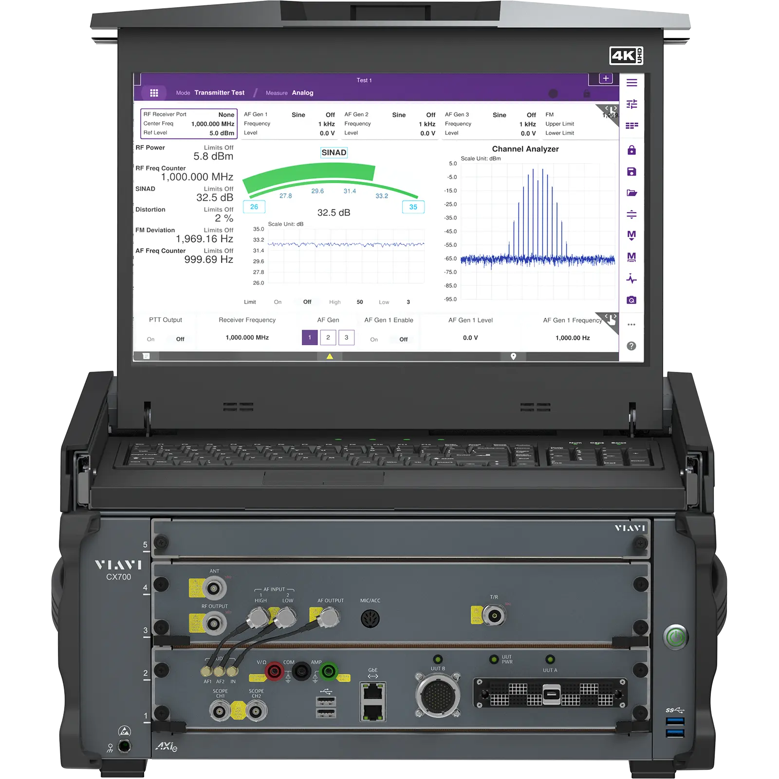
VIAVI CX700 ComXpert Radio Test System for Analog, Digital and Software Defined Radios
Automated radio test system that covers 9 kHz to 6 GHz with 100 MHz instantaneous bandwidth, for commercial, tactical and military radios.
- Frequency range
- 100 kHz to 3 GHz
- Frequency range
- 3 GHz to 6 GHz
- Frequency accuracy
- Same as timebase
- Frequency resolution
- 0.1 Hz
Overview
The VIAVI CX700 ComXpert Radio Test System is an automated radio communications test solution for commercial, tactical and military applications in production, depot-level and field environments. It follows the earlier TS-4317 and 7200B models and is an SCA-compliant modular platform that combines RF test functions, a graphical user interface and automation capability.
The CX700 tests analog and digital frequency-hopping radios as well as software defined radios. In addition to its RF generator and receiver, it includes a 2-channel oscilloscope, a digital multimeter (DMM), real-time I/Q record and playback, and a frequency hop burst power meter.
The instrument covers frequencies up to 6 GHz with 100 MHz instantaneous bandwidth. Meters use pass/fail color coding, and an Auto-Test framework supports automated test sequences. The user interface uses multiple tabs, similar to an internet browser, and the unit has a collapsible high-resolution touch-screen display with a keyboard and trackpad.
Radio interface and packaging
A fully programmable 168-pin zero insertion force (ZIF) connector gives access to the DMM, oscilloscope, Ethernet, RX/TX, USB, RS-232, RS-422, GPIO and 5 V / 3.3 V TTL in/out signals, and is compatible with legacy VIAVI test sets. A 55-pin MIL circular connector provides additional I/O. The packaging complies with MIL-PRF-28800F Class 3, so the CX700 can be used in the laboratory and in the field. A rack mount option is available.
Key Features
- Receiver frequency range from 9 kHz to 6 GHz
- 100 MHz instantaneous bandwidth
- Standard AM/FM/PM/SSB modulation and demodulation modes
- Power meter, spectrum analyzer, audio generator, distortion meter, SINAD meter, audio analyzer, frequency counter and frequency reference
- 2-channel oscilloscope and digital multimeter (DMM)
- Real-time I/Q record and playback
- Frequency hop burst power meter
- Fully programmable 168-pin zero insertion force (ZIF) connector with DMM, scope, Ethernet, RX/TX, USB, RS-232, RS-422, GPIO, and 5V and 3.3V TTL in/out
- Collapsible high resolution touch-screen display and keyboard/trackpad
- Multiple tab user interface, similar to an internet browser
- Intelligent color-coded meters for at-a-glance test verification
- Auto-Test framework for automated testing
- SCA-compliant modular platform
- MIL-PRF-28800F Class 3 packaging with rack mount option available
Specifications
|
Frequency range
CX700
|
100 kHz to 3 GHz |
|---|---|
|
Frequency range
CX700-F6GHZ
|
3 GHz to 6 GHz |
| Frequency accuracy | Same as timebase |
| Frequency resolution | 0.1 Hz |
| T/R port output level range | -130 dBm to -30 dBm (>1 MHz); -140 dBm to -30 dBm (>10 MHz); -130 dBm to -30 dBm (>1 GHz) |
| GEN port output level range | -120 dBm to +17 dBm (>1 MHz); -130 dBm to +17 dBm (>10 MHz); -120 dBm to +17 dBm (>1 GHz) |
| T/R port output level accuracy |
±1 dB
>1 MHz
|
| GEN port output level accuracy | ±1 dB (> -120 dBm); ±2 dB (≤-120 dBm & ≥-130 dBm) ±1 dB typical |
| Output level resolution | 0.1 dB |
| Maximum bandwidth | 100 MHz IBW |
| VSWR, T/R port | ≤1.1 (1 MHz to 1 GHz); <1.2 (1 GHz to 6 GHz) |
| VSWR, GEN port | ≤1.4 (1 MHz to 1 GHz); <1.5 (1 GHz to 6 GHz) |
| Phase noise |
-112 dBc/Hz
at 10 kHz offset at 500 MHz
|
| Harmonics, GEN port |
-35 dBc
for output level <+10 dBm
|
| Harmonics, T/R port |
-35 dBc
for output level <-30 dBm
|
| Non-harmonics | <-50 dBc (<2.8 GHz); <-45 dBc (>2.8 GHz) |
| Residual AM |
<0.1% rms
for frequency ≤1 GHz & >1 MHz (post-detection BW: 300 Hz to 3 kHz)
|
| Residual FM |
<3 Hz rms 300 Hz to 3 kHz
for frequency < 1 GHz & > 1 MHz (post-detection BW: 300 Hz to 3 kHz)
|
| I/Q file modulation | Allows user to run arbitrary waveforms as modulation source; browse and load I/Q file |
| Modulation modes | AM, FM, PM, SSB |
|---|---|
| FM range | Off, 0 to ± 100 kHz |
| FM accuracy | < ±2.5% of setting |
| FM rate | 20 Hz to 20 kHz, useable to 100 kHz |
| AM range | 0% to 100% |
| AM accuracy | < ±5% of setting |
| PM range | Off, 0 radians to 6.3 radians |
| PM accuracy | ±2.5% of setting |
| SSB range | 300 Hz to 3 kHz |
| SSB carrier suppression | >70 dB |
| SSB sideband suppression | >60 dB |
| Modulation waveforms | Sine, Square, Triangle, Ramp |
| Number of internal modulation sources | 3 |
| Internal source sine wave range | DC to 100 kHz |
| Internal source square wave range | 20 Hz to 20 kHz |
| AM distortion |
<1% (700 Hz to 1.1 kHz); <1.5% (100 Hz to 6.0 kHz); <2.5% (> 6.0 kHz to 10.0 kHz)
30% to 70% modulation
|
| FM distortion | <0.7% (700 Hz to 1.1 kHz); <1% (20 Hz to 20 kHz) |
| PM distortion | <2% (1 kHz rate, ≥ 0.3 radians) |
|
Frequency range
CX700
|
9 kHz to 3 GHz |
|---|---|
|
Frequency range
CX700-F6GHZ
|
3 GHz to 6 GHz |
| Frequency resolution | 1 Hz |
| Maximum input level, ANT port |
+20 dBm max
preamp off and frequency >1 MHz
|
| Maximum input level, T/R port | 50 W continuous at 50°C ambient; 50-150 W, 30 s on, 2 min off at 50°C ambient; 150-200 W, 15 s on, 2 min off at 50°C ambient |
| Spurious response, input related | ≤-65 dBc typical |
| Spurious response, non-input related | ≤-95 dBm typical |
| Phase noise | -112 dBc/Hz at 10 kHz offset at 500 MHz; -110 dBc/Hz at 10 kHz offset at 1000 MHz |
| Dynamic range | 2/3 * (TOI-DANL) = 109 dB |
| TOI |
+20 dBm (0 atten), >+1 dBm (preamp)
1 MHz to 1 GHz
|
| DANL |
<-144 dBm (0 atten), <-162 dBm (preamp)
1 Hz RBW @ 1 GHz
|
| Analog bandwidth | 100 MHz (wideband VSA), 8 MHz (narrowband) |
| IF bandwidth | 5 kHz, 6.25 kHz, 8.33 kHz, 10 kHz, 12.5 kHz, 25 kHz, 30 kHz, 100 kHz, 300 kHz |
| FM deviation range | 0 Hz to 100 kHz |
|---|---|
| FM modulation rate range | 10 Hz to 40 kHz, useable to 100 kHz |
| FM accuracy | ±2.0%, ±1.0% (rate 1.5 kHz to 3 kHz) |
| FM detector modes | RMS, RMS*√2, +PK, -PK, ±PK/2 |
| Residual FM |
≤3 Hz (300 Hz to 3 kHz)
frequency <1 GHz
|
| AM depth | 0% to 100% |
| AM modulation rate range | 10 Hz to 20 kHz |
| Residual AM | <0.1% (300 Hz to 3 kHz) |
| PM range | 0 radians to 10 radians |
| PM rate | 10 Hz to 20 kHz |
| PM resolution | 0.01 rad for ≤ 5 rad; 0.1 rad for > 5 rad |
| SSB modes | SSB-USB, SSB-LSB |
| SSB measurements | Frequency error, Power (RMS), Power (PEP) |
| AF output impedance | <4 Ω |
|---|---|
| AF max output current | 100 mA |
| AF generator frequency range | DC to 100 kHz (sine only) |
| AF generator level range | 0 to ±4 V pk into 50 Ω; 0 to ±7 V pk into 150 Ω; 0 to ±8 V pk into 600 Ω |
| AF generator THD+N |
<-75 dB
for frequency 1 kHz and level 1 Vrms
|
| Audio input frequency | DC to 100 kHz |
| Audio input impedance |
150 Ω (UUT-A), 300 Ω, 600 Ω, 100 kΩ single ended, ±1 % shunted by ≤300 pF, 200 kΩ differential, ±8 %
max input voltage 30 VRMS; max input power 1.5 W
|
| Audio input level range | 50 mVrms to 30 Vrms |
| Audio analyzer FFT windows | Flat top, rectangular, Hamming, Hann, Blackman-Harris |
| Audio filters, lowpass | 300 Hz, 3 kHz, 3.4 kHz, 5 kHz, 15 kHz, 20 kHz |
| Audio filters, highpass | 20 Hz, 50 Hz, 300 Hz |
| Audio filters, other | C-MSG, CCITT, A-Weighted, C-Weighted |
| De-emphasis | 75 µs, 750 µs |
| Power meter frequency range | 100 kHz to 3 GHz (CX700); 3 GHz to 6 GHz (CX700-F6GHZ) |
|---|---|
| Power meter measurement modes | RMS, average RMS, minimum, maximum |
| Power meter input range, T/R port | -20 dBm to +53 dBm |
| Power meter input range, ANT port | -60 dBm to +10 dBm |
| Power meter accuracy, T/R port | >0.02 mW level, ± 10%; ±0.4 dB (frequency <1 GHz & >1 MHz), ±0.5 dB (elsewhere) |
| Power meter accuracy, ANT port | >-80 dBm, ±0.6 dB (frequency <1 GHz & >1 MHz), ±0.9 dB (elsewhere) |
| Power meter units | Watts, mWatts, and dBm (absolute and relative) |
| Burst power meter input range | 1 to 100% |
| Burst power meter accuracy |
±0.2% Power Envelope Drop Out
10 - 90% duty cycle, 1 Hz to 10kHz, <20% drop out
|
| RF error meter range | 0 Hz to ±100.0 kHz (in 4 decade ranges) |
|---|---|
| RF error meter input level range | T/R Port -20 to 51 dBm; ANT Port -60 to +17 dBm (-80 to -20 dBm w/pre-amp) |
| AF counter frequency range | DC to 100 kHz |
| AF level meter input range | 20 mVrms to 30 Vrms for Hi-Z / 600 Ω Impedance; 20 mVrms to 7 Vrms for 150 Ω / 300 Ω Impedance |
| SINAD meter measurement range |
0 dB to 63 dB
frequency range 50 Hz to 10 kHz
|
| SINAD meter accuracy | ±1 dB ±1 count |
| Distortion meter measurement range |
0% to 100%
frequency range 50 Hz to 10 kHz
|
| Distortion meter accuracy | ±3% of reading + 0.1% distortion for 1% to 20% |
| S/N meter measurement range |
0 to 63 dB
frequency range 50 Hz to 10 kHz; accuracy <1 dB
|
| EVM range |
0 - 100%
resolution 0.01%
|
|---|---|
| EVM input level | T/R Port: >-20 dBm; ANT Port: >-60 dBm |
| 8PSK modulation residual |
Residual (floor) <1.5% rms
for frequency 1 GHz and IBW 10 MHz
|
| 16QAM modulation residual |
Residual (floor) < 1.2% rms
for frequency 1 GHz and IBW 10 MHz
|
| FSK meter range |
1 kHz - 10 kHz
accuracy ±25 Hz
|
| Modulation fidelity range | 0 - 30% |
| Frequency range | 9 kHz to 3 GHz (CX700); 3 GHz to 6 GHz (CX700-F6GHZ) |
|---|---|
| Span modes | Center / Span and Zero Span and Full |
| Span range |
1 kHz/div to 100 MHz/Div plus Zero span & full span
10 divisions in a 1-2-5 sequence
|
| DANL |
-162 dBm from 1MHz to 1100 MHz; -163 dBm from 1100 MHz to 2300 MHz; -160 dBm from 1100 MHz to 4500 MHz; -158 dBm from 4500 MHz to 6000 MHz
dBm/Hz, Ant Port, Receiver preamp on (-40 dBm), 1 Hz RBW, averaging on, 50Ω termination
|
| RBW | 25 Hz to 6 MHz; 1 Hz to 50 kHz in Channel analyzer |
| VBW | 100 Hz to 5 MHz |
| Sweep time range | 0.4 ms to 1000 s |
| Spurious free dynamic range | ≥80 dB |
| Display range | 1 dB/div to 20 dB/div with 10 divisions |
| FFT / channel analyzer span |
2 kHz to 8 MHz
IF bandwidth 10 MHz; RBW 1 Hz to 50 kHz
|
| Zero span analyzer sweep time range | 24 µs to 200 s |
| Tracking generator output ports |
GEN, T/R
level range and accuracy same as RF Generator
|
| Channels | 2 |
|---|---|
| Internal sample clock frequency | 40 Ms/s sampling clock, 1 uSec/Div to 1 Sec/Div |
| Trigger modes |
Automatic, Normal, Single Shot
sources CH1, CH2, External
|
| Horizontal sweep per div | 20 µs to 1 s/div |
| Vertical range | 0.1 mV/div to 20 V/div |
| Bandwidth |
100 kHz
The product web page describes a 2-channel 125 MHz oscilloscope; the datasheet value is given here
|
| Input range | 20 mV to 30 Vrms (42.4 Vpk) |
| Input impedance |
1 MΩ single ended, ±1 % shunted by ≤ 300 pF, 200 kΩ differential, ±8 %
max input voltage 30 VRMS
|
| Sample length | 4 Msamples memory or file on SSD, limited by SSD free space |
|---|---|
| Sample rate | Variable to support up to 100 MHz of analog bandwidth |
| DC voltage range |
0.1 to 300 V
scales 20 mV, 200 mV, 2 V, 20 V, 200 V, 2000 V
|
|---|---|
| DC voltage accuracy | ±1% full scale (DC), ±1 count |
| DC current range | 20 mA, 200 mA, 2 A, 20 A (with shunt) |
| Resistance range |
200 Ω to 200 M Ω
accuracy ±1% Ω
|
| AC voltage accuracy | ±5% full scale, ±1 count (50 Hz to 10 kHz) |
| AC current range | 10 mA to 2 A, 10 A (with external shunt) |
| Resolution |
5 1/2 digits
The product web page describes a 6 ½ digit DMM; the datasheet value is given here
|
| Timebase accuracy | ±0.01 ppm max (0°C to 70°C) |
|---|---|
| Aging | ±0.05 ppm/year max; ±0.1 ppm/year max (first year) |
| External reference | 10 MHz |
| Frequency reference input |
100 MHz
duty cycle 45 - 55%
|
| Frequency reference output |
10 MHz / 100 MHz
selectable; 3.3 V CMOS into 50 Ω
|
| GNSS timing (SMA) constellations | GPS (L1), GLONASS (L1, FDMA), Galileo (E1) |
| GNSS 1 PPS accuracy |
UTC ±10 ns
1-sigma, 1 satellite in track 24 hours
|
| Serial ports | 2x RS-232 (422, 485) synchronous + 2x RS-232 (422, 485) asynchronous ports on UUT-(A/B) connectors |
|---|---|
| Ethernet | 2x RJ45 1GbE on RIM Tray + 1x RJ45 1GbE back of the chassis + 1x 1GbE on the ZIF tied to first Ethernet device. 1x additional 1GbE on UUT-A tied to the second Ethernet device (Different IP stacks) |
| UUT-A | 168-pin ZIF connector compatible with legacy VIAVI test sets |
| UUT-B | 55-pin MIL circular connector with additional I/Os for future-proofing |
| USB | 3.1 ports (x2 type A) on the rear of the unit, USB 2.0 ports (x2) on UUT-A connector, USB 2.0 ports (x2 type A) on the RIM tray front panel, USB 3.1 ports (x2 type A) on the front of the chassis |
| Removable storage | M.2 SSD |
| Video/monitor | Display Port |
| External trigger input (BNC) |
Max input level ±10 V, input impedance 1 kΩ
minimum threshold (programmable) 250 mV
|
| External trigger output (BNC) |
3.3 V CMOS
output load 50 Ω
|
| AC operating voltage range | 100 - 300 VAC |
|---|---|
| AC input frequency range | 47 - 66 Hz |
| Efficiency (typical) | 91 - 95% |
| Holdup time | 20 ms |
|
Built-in power supply Output A
CX700-PS, CX700-PS-NOKVM
|
5-40 V DC, 20 A max, available on UUT-A connector |
|
Built-in power supply Output B
CX700-PS, CX700-PS-NOKVM
|
2-28 V DC, 5A max, available on UUT-B connector |
|
Built-in power supply Output C
CX700-PS, CX700-PS-NOKVM
|
5 V DC, 4 A Max, available on UUT-B connector |
| Height | 24.4 cm (9.6 in) |
|---|---|
| Width | 46.2 cm (18.2 in) |
| Depth | 49.0 cm (19.3 in) |
| Weight |
34.3 kg (76 lbs)
test set only, additional weight for accessories and case
|
| Operating temperature | 0°C to 50°C |
| Non-operating temperature | -40°C to 71°C |
| Relative humidity | 95%±5% from 10°C to 30°C; 75%±5% from 31°C to 40°C; 45%±5% from 41°C to 50°C |
| Altitude | 4600 meters |
| Vibration | Random 5-500 Hz per Table 3 of MIL-PRF-28800F Class 3 |
|---|---|
| Shock, functional | 30 G half-sine shock pulses per 4.5.5.4.1 of MIL-PRF-28800F Class 3 |
| Bench handling | MIL-PRF-28800F Class 3 |
| Transit drop | MIL-PRF-28800F Class 3 |
| EMC | MIL-PRF-28800F, EN 61326-1 Class A (CE), EN 61000-3-2, EN 61000-3-3 |
| Safety standards | UL 61010-1, EN 61010-1, EN 61010-2-30, CSA C22.2 No. 61010-1-12, ETSI EN 301 489-1, ETSI EN 301 489-19, FCC Part 15 Subpart B, ICES-003 |
Specifications are taken from the manufacturer's documentation. See the datasheet for complete and current values.
Applications
- Tactical radio testing
- Military radio testing
- Commercial radio communications testing
- Analog and digital frequency-hopping radio testing
- Software defined radio testing
- Production test
- Depot-level maintenance
- Field testing
Options & Accessories
| Option | Description |
|---|---|
| CX700-F6GHZ | 3 GHz to 6 GHz frequency range — Extends RF generator, receiver, spectrum analyzer and meter frequency coverage to 3 GHz to 6 GHz |
| CX700-PS | Built-in Power Supply with 3 Outputs — Output A 5-40 V DC on UUT-A; Outputs B and C on UUT-B |
| CX700-PS-NOKVM | Built-in Power Supply with 3 Outputs (NOKVM) |
Documents & Resources
Related Products
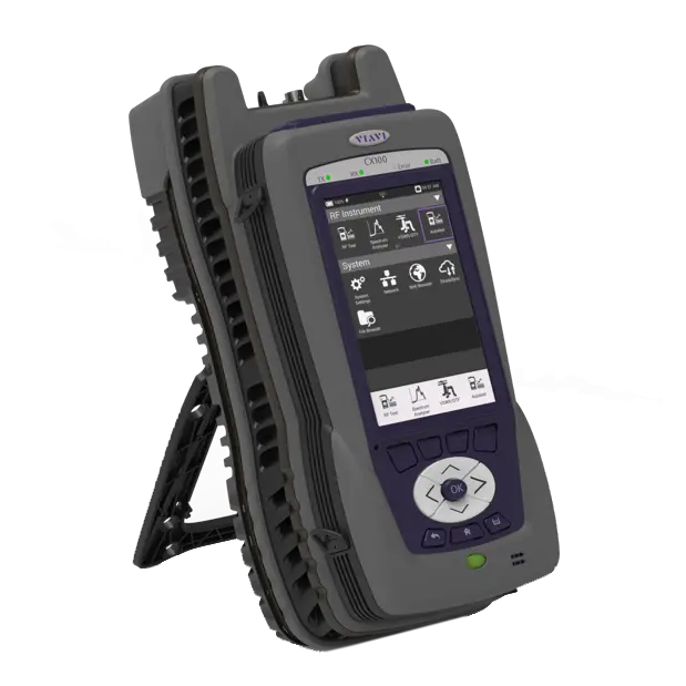
Rugged handheld communications service monitor with a 6 GHz frequency range and a 1-port vector network analyzer for field radio testing.
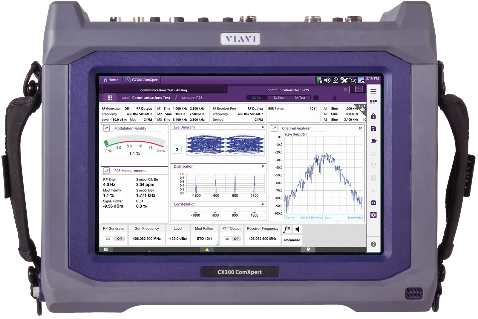
Portable communications service monitor for analog and digital radio testing from 100 kHz to 6 GHz, with optional Auto-Test alignment.
Hybrid bench and field test set for analog and digital land mobile radios, with a 1 GHz RF generator and receiver and a 12 in touch screen.