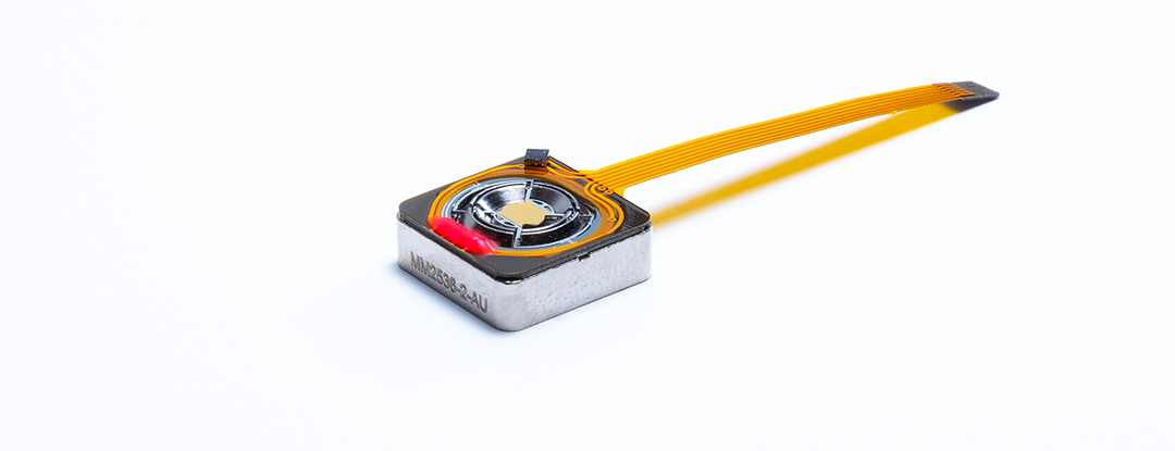
Sercalo MM2536-2 Dual-Axes Magnetic MEMS Mirror, 2.5 × 3.6 mm Aperture
Dual-axes magnetic MEMS mirror with a 2.5 × 3.6 mm aperture and ±5° linear mechanical tilt for static and dynamic beam steering.
- Mass (without electronics)
- 6 g
- Dimensions (without connector)
- 14.0 × 14.0 × 6.0 mm
- Mirror dimension (DX × DY)
- 2.5 × 3.6 mm²
- Mounting
- Four tapped holes for M2 screws
Overview
The Sercalo MM2536-2 is a dual-axes magnetic MEMS mirror for static and dynamic beam steering. It has a 2.5 × 3.6 mm aperture, and the tilt angle of up to ±5° is set linearly by the drive current. It is suited to applications where small size and low power consumption matter.
Each device carries a small EEPROM that stores its main parameters, such as DC gain, coil resistance and resonance frequency. The device can therefore be calibrated for either current-driven or voltage-driven electronics. A product report sheet with measured gain values ships with each device, and the same values are saved in the device memory.
Operating principle
The device combines the mirror surface, a voice-coil actuator and torsion bars that act as mechanical springs. When current flows through the coil around the mirror, it interacts with an external magnetic field. The resulting Lorentz force produces a torque that rotates the mirror. The torsion bars support the mirror and supply a restoring force that limits and stabilises the rotation. Sercalo's design directs the magnetic field to a specific zone, which improves performance at low power consumption and allows a larger mirror. The device supports both pointing and dynamic scanning.
Drive and interface
Unlike electrostatic comb-driven mirrors, magnetic actuation is driven by current, so a 5 V driver is enough to power the MM2536-2. In the standard option, the coils are driven and the EEPROM is read over an FFC connector that includes a 1-Wire data line. The device mounts to a reference surface with four M2 tapped holes. Because the device contains permanent magnets, the manufacturer recommends using non-magnetic tools, screws and nearby materials.
Key Features
- Dual-axes beam steering
- ±5° mechanical tilt on both axes
- Static and dynamic beam steering
- Tilt angle set linearly with the drive current
- Magnetic actuation powered by a 5 V driver
- Onboard EEPROM holding DC gain, resistance and resonance frequency parameters
- Ready for current- or voltage-driven electronics
- 2.5 × 3.6 mm mirror aperture
- Gold or aluminum mirror coating
Specifications
| Mass (without electronics) |
6 g
Typ.
|
|---|---|
| Dimensions (without connector) |
14.0 × 14.0 × 6.0 mm
Typ.
|
| Mirror dimension (DX × DY) |
2.5 × 3.6 mm²
Typ.
|
| Mounting |
Four tapped holes for M2 screws
Non-magnetic screws recommended
|
| Supply Current (Axis X) |
33 mA/°
Typ.
|
|---|---|
| Supply Current (Axis Y) |
30 mA/°
Typ.
|
| Power consumption (Total) |
600 mW
Max.
|
| Coil Resistance (Axis X) |
10 Ω
Typ.
|
| Coil Resistance (Axis Y) |
10 Ω
Typ.
|
| Resonance Frequency (Axis X) |
350 to 400 Hz
Min. to max.
|
| Resonance Frequency (Axis Y) |
200 to 250 Hz
Min. to max.
|
| Tilt Angle Range (both axes) |
-5 to 5 °
Min. to max.; mechanical tilt
|
| Connector |
FFC connector with EEPROM 1-Wire interface
Standard option, without optical feedback
|
|---|---|
| Pin 1 | X+ (X axis coil positive input) |
| Pin 2 | X- (X axis coil negative input) |
| Pin 3 | Y+ (Y axis coil positive input) |
| Pin 4 | Y- (Y axis coil negative input) |
| Pin 5 | GND (Ground) |
| Pin 6 | DATA (EEPROM 1-Wire Line) |
|
Operating Wavelength
AU
|
IR
Gold coating
|
|---|---|
|
Operating Wavelength
AL
|
Visible
Aluminium coating
|
|
Reflectivity
AU
|
98% @1550nm
Gold coating
|
|
Reflectivity
AL
|
>88 %
Aluminium coating
|
| Wavefront Error |
<300 nm
Gold and aluminium coatings
|
|
Roughness
AU
|
<1 nm
Gold coating
|
|
Roughness
AL
|
<1.5 nm
Aluminium coating
|
| Operating Temperature |
-5 to 85 °C
Min. to max.
|
|---|---|
| Storage Temperature |
-40 to 85 °C
Min. to max.
|
| Maximum supply current per axis (DC) |
200 mA
Over the full operating temperature range without irreversible damage
|
|---|---|
| Maximum current ramp (DC) |
2 A/s
Large DC current steps can damage the device through mechanical overshoot
|
Specifications are taken from the manufacturer's documentation. See the datasheet for complete and current values.
Applications
- Optical beam steering
- Optical beam scanning
- Static beam pointing
- Low-power, compact optical systems
Included
- Product report sheet with measured gain values
Options & Accessories
| Option | Description |
|---|---|
| AU | Gold Coating — Gold mirror coating for IR operation |
| AL | Aluminum Coating — Aluminum mirror coating for visible operation |
| FB | Feedback Sensor — Optional feedback sensor (label suffix [FB]) |
Documents & Resources
Related Products
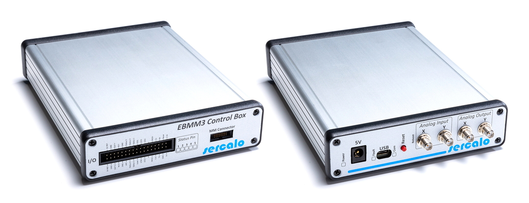
Driver and controller kit for Sercalo magnetic MEMS mirrors, with open-loop or closed-loop dual-axis control over a UART CLI or ±5V analog inputs.
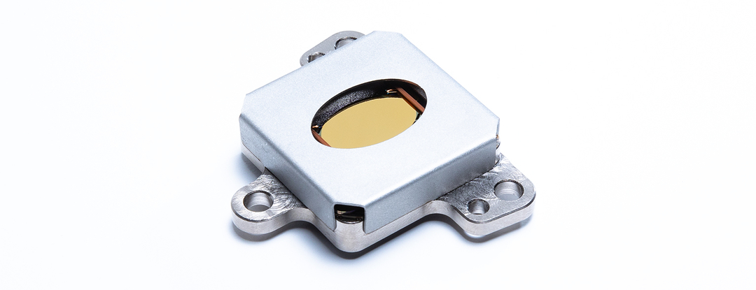
Dual-axis fast steering magnetic MEMS mirror with a 16.0x11.0mm aperture and +/-1.5° linear mechanical tilt for static and dynamic beam steering.