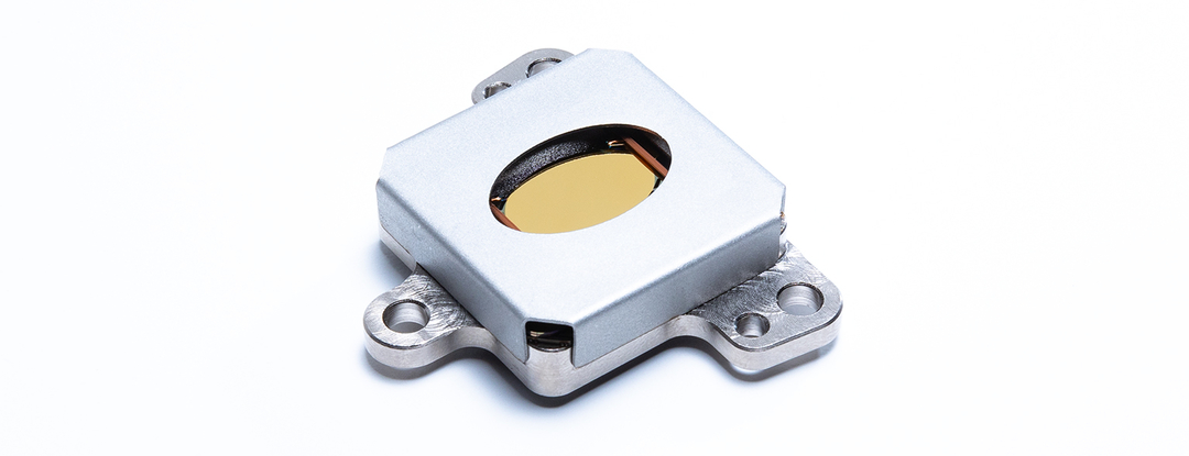
Sercalo MM160110-2-15 Fast Steering Magnetic MEMS Mirror (FSM), Dual-Axis 16x11mm
Dual-axis fast steering magnetic MEMS mirror with a 16.0x11.0mm aperture and +/-1.5° linear mechanical tilt for static and dynamic beam steering.
- Mass
- 50 g
- Dimensions (without connector)
- 51x42x10 mm
- Aperture
- 16.0x11.0mm
- Mounting
- Four holes for M4 screws
Overview
The Sercalo MM160110-2-15 is a dual-axis fast steering magnetic MEMS mirror (FSM, also called a fine steering mirror) designed for static and dynamic beam steering. It provides a large 16.0x11.0mm reflective aperture and is driven linearly with current up to a tilt angle of +/-1.5°. The mirror is designed for DC operation as well as scanning.
Operating principle
The device combines the mirror surface, a voice-coil actuator and torsion bars acting as mechanical springs. Current passing through a coil embedded around the mirror interacts with an externally applied magnetic field, producing a Lorentz-force torque that rotates the mirror. The torsion bars support the mirror and provide a restoring force that stabilises and limits the rotation. The design redirects the magnetic field to a specific zone to increase performance at low power consumption, which allows mirror sizes up to 16mm and supports both pointing and dynamic scanning.
Calibration and interface
Each mirror carries a 1024-bit 1-Wire EEPROM (DS2431) holding its main parameters, such as DC gain, resistance and resonance frequency, so it can be used with current- or voltage-driven electronics. The actuator coils are accessed through 1.27mm pitch 4-pin holes or a 6-pin FPC connector. The mirror is available with gold or aluminium coating and in different surface flatness grades.
Key Features
- Dual-axis beam steering with 16.0x11.0mm aperture
- +/-1.5° mechanical tilt on both axes
- Static and dynamic beam steering
- Linear actuation: tilt angle set linearly with the current
- Magnetic (voice-coil / Lorentz force) actuation
- Onboard 1-Wire EEPROM storing mechanical and electrical parameters for current or voltage drivers
- Gold or aluminum mirror coating
- 6-pin FPC connector and 1.27mm pitch 4-pin through-holes for coil access
- Four mounting holes for M4 screws
Specifications
| Mass |
50 g
max
|
|---|---|
| Dimensions (without connector) |
51x42x10 mm
typ.
|
| Aperture | 16.0x11.0mm |
| Mounting |
Four holes for M4 screws
Nonmagnetic screws recommended
|
| Actuating current (X axis) |
27 mA/°
typ.; min 22.0, max 32.0
|
|---|---|
| Actuating current (Y axis) |
22 mA/°
typ.; min 18.5, max 25.5
|
| Power consumption (DC max angle) |
0.6 W
max
|
| Coil resistance (X axis) |
96.0 Ω
typ.; min 92.0, max 100.0
|
| Coil resistance (Y axis) |
175.0 Ω
typ.; min 167.0, max 183.0
|
| Resonance frequency (X axis) |
315.0 Hz
typ.; min 290.0, max 340.0
|
| Resonance frequency (Y axis) |
165.0 Hz
typ.; min 150.0, max 180.0
|
| Tilt angle (both axes) |
-1.5 to 1.5 °
Exceeding the tilt limitation by a few degrees will break the torsion bars
|
| Connector | 6-pin FPC connector (type MOLEX 505110-0692) |
|---|---|
| Coil test access | 1.27mm pitch 4-pin holes |
| Pin assignment | 1 X+, 2 X-, 3 Y+, 4 Y-, 5 GND (EEPROM), 6 DATA (1-Wire EEPROM) |
| EEPROM |
1024-Bit, 1-Wire EEPROM of type DS2431
Stores device information and actuator parameters
|
|
Operating wavelength
AU
|
infrared |
|---|---|
|
Operating wavelength
AL
|
visible |
|
Reflectivity
AU
|
98% @1550nm |
|
Reflectivity
AL
|
> 85% |
|
LIDT
AU
|
0.16 J/cm2
1030nm, 10ps
|
|
LIDT
AL
|
0.08 J/cm2
515nm, 10ps
|
|
Surface flatness (RMS)
AU
|
< 50 nm (Grade 5) or < 100 nm (Grade 10) |
|
Surface flatness (RMS)
AL
|
< 100 nm (Grade 10) or < 200 nm (Grade 20) |
|
Roughness
AU
|
<1 nm |
|
Roughness
AL
|
< 1.5 nm |
| Sinus vibration (10 – 80 Hz) |
4 – 30 g
With actuator coils connected
|
|---|---|
| Sinus vibration (80 – 100 Hz) |
30 g
With actuator coils connected
|
| Random vibration (20 – 100 Hz) | 12 dB/oct |
| Random vibration (100 – 300 Hz) | 1.5 g2/Hz |
| Random vibration (300 – 2000 Hz) | -8 dB/oct |
| Shock (100 Hz) | 30 g |
| Shock (1 kHz) | 500 g |
| Shock (10 kHz) | 500 g |
| Operating temperature | -5 to 85 °C |
|---|---|
| Storage temperature | -40 to 85 °C |
| Maximum supply current X axis (DC) | 50 mA |
|---|---|
| Maximum supply current Y axis (DC) | 40 mA |
| Maximum current ramp (DC) |
2 A/s
Voltage driver recommended for DC use
|
Specifications are taken from the manufacturer's documentation. See the datasheet for complete and current values.
Applications
- Optical beam steering
- Optical beam scanning
- Fine pointing
Included
- Measurement report
- Protective tape over the aperture
- Membrane box
Options & Accessories
| Option | Description |
|---|---|
| AU | Gold Coating — Infrared operating wavelength; surface flatness grade 5 (<50nm RMS) or 10 (<100nm RMS) |
| AL | Aluminum Coating — Visible operating wavelength; surface flatness grade 10 (<100nm RMS) or 20 (<200nm RMS) |
| 5 | Surface flatness < 50nm RMS |
| 10 | Surface flatness < 100nm RMS |
| 20 | Surface flatness < 200nm RMS |