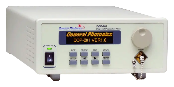
DOP-201 Degree of Polarization Meter
Benchtop meter that measures the degree of polarization and optical power of a light source over 1440 to 1620 nm in 30 ms.
- Operating wavelength range
- 1440 to 1620 nm standard
- DOP resolution
- 0.01%
- DOP accuracy
- ±0.5% (single sample), ±0.2% (10 sample average)
- DOP repeatability
- ±0.2% (10 sample average)
Overview
The DOP-201 Degree of Polarization Meter measures the degree of polarization (DOP) and the optical power of a light source under test at the same time. It pairs a low activation loss fiber squeezer polarization controller with a patented maximum-minimum search method. This lets it measure both low and high DOP values without ambiguity in 30 ms, across a wavelength range that covers the S, C and L bands without calibration.
Measurement principle
DOP is the ratio of the power in the fully polarized component of a light beam to the beam's total power. Polarimeter-based systems can be inaccurate for low-DOP sources, and polarization scrambler-based instruments are less accurate for high-DOP sources. The DOP-201's method rests on the physical properties of partially polarized light rather than on intermediate parameters, so it does not need instrument calibration. The instrument suits CW or quasi-CW sources with slow polarization variation. It is not intended for polarization-scrambled sources.
Measurement modes
Because DOP and optical power are measured together, the instrument can show how DOP depends on power and can confirm low insertion loss during depolarizer manufacturing. Besides DOP/power mode, the DOP-201 derives signal-to-noise ratio (SNR) from DOP. It also measures the noise figure of in-line optical amplifiers such as EDFA and Raman amplifiers by comparing OSNR with and without the amplifier.
Integration
The instrument comes in a 2U half-rack enclosure with an OLED display. A 0 to 5 V analog output gives a monitor voltage proportional to DOP over a user-set DOP range. TTL input and output triggers support synchronization with other equipment. Remote control uses RS-232, USB, Ethernet or GPIB, with SCPI and legacy GP command formats.
Key Features
- Accurate for both high and low DOP values
- Wide wavelength range
- Analog output for automated testing
- 30 ms measurement speed
- Simultaneous DOP and optical power measurement
- DOP measurement is wavelength independent and requires no calibration
- SNR and amplifier noise figure measurement modes
- Front panel real time OLED display
- TTL input and output triggers on BNC connectors
- USB, Ethernet, RS-232 and GPIB interfaces
Specifications
| Operating wavelength range | 1440 to 1620 nm standard |
|---|---|
| DOP resolution | 0.01% |
| DOP accuracy |
±0.5% (single sample), ±0.2% (10 sample average)
At 23 ± 5°C
|
| DOP repeatability | ±0.2% (10 sample average) |
| DOP range | 0 – 100% |
| Measurement speed | 30 ms/measurement for input > -30 dBm |
| Operating power range |
-40 to 6 dBm
Web page states −40 to +6 dBm
|
| Optical power accuracy | ±0.25 dB |
| Wavelength calibration for power measurement | 1440 to 1620 nm |
| Front panel display | OLED graphic display |
|---|---|
| Analog output | 0 to 5 V max range, user configurable; monitor voltage for DOP |
| Input/output triggers | TTL pulse, BNC connector |
| Power supply | 100 – 240 VAC, 50 – 60 Hz |
| Communication interfaces | USB, Ethernet, RS-232, and GPIB |
| GPIB address | 1-30 |
| RS-232 baud rate |
110, 300, 600, 1200, 2400, 4800, 9600, 19200, 28800, 38400, 43000, 56000, 57600, 115200, 128000, 230400, 460800
Default 9600 bps
|
| Dimensions |
2U 19” half rack width 14" (L) x 8.5" (W) x 3.5" (H)
Rack mount kit available
|
|---|---|
| Weight | 7.5 lb |
| Optical connectors |
FC/PC, FC/APC
Others on request (specify when ordering)
|
| Operating temperature | 0 to 50 °C |
| Storage temperature | -20 to 70 °C |
| Wavelength code |
1 = 1440 - 1620nm
Ordering format DOP-201-[wavelength]-[connector]
|
|---|---|
| Connector type | FC/PC, FC/APC, Others specify |
Specifications are taken from the manufacturer's documentation. See the datasheet for complete and current values.
Applications
- Manufacturing test of fiber optic assemblies
- Fiber optic gyroscopes
- Depolarizer manufacturing and QC
- Fiber gyro coil characterization
- ASE and SLED source characterization
- Raman amplifier block manufacturing
- ROADM manufacturing
- Amplifier noise figure measurement
- Characterization of low and high DOP light sources
Included
- Power cord
- RS-232 cable (straight-wired)
- USB cable
- User guide
- Software CD
Options & Accessories
| Option | Description |
|---|---|
| RCK-001 | Rack Mount Kit |
Documents & Resources
Related Products
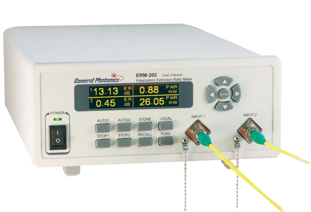
Rotating-polarizer polarization extinction ratio meter with a PER dynamic range of 50 dB, available in single or dual channel versions.
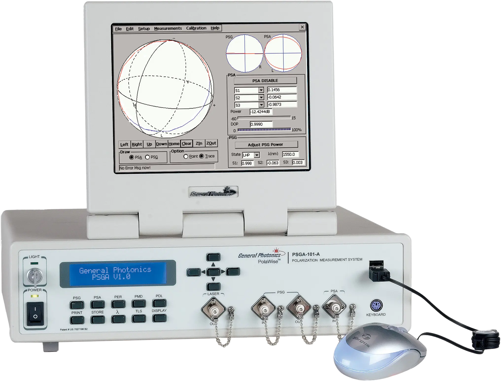
Polarization measurement system that measures SOP, DOP, DGD, SOPMD, PDL and PER of light and optical components versus wavelength.
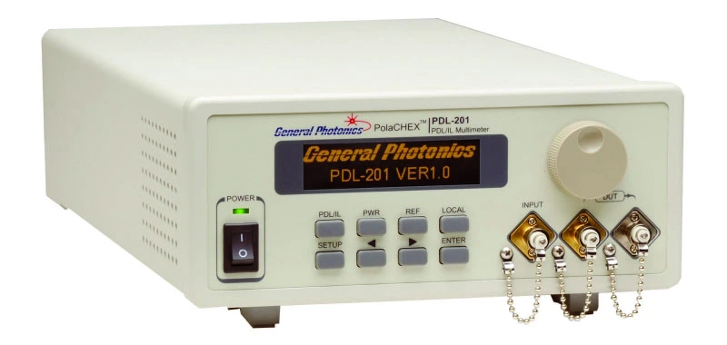
Benchtop multimeter that measures polarization dependent loss, insertion loss and optical power from 1260 to 1620 nm in 30 ms.
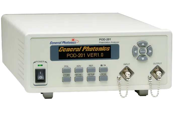
In-line fiber-coupled polarimeter that measures all four Stokes parameters at up to 4M samples/s to report SOP, DOP and optical power.
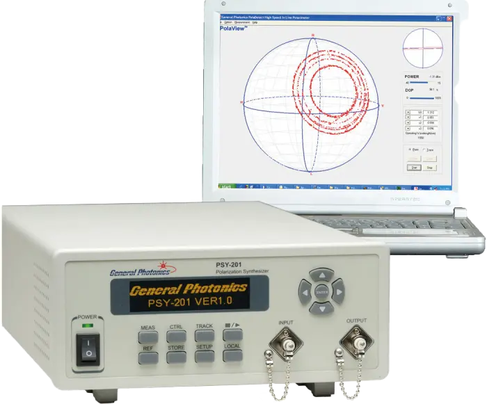
Deterministic polarization controller and polarimeter that generates, maintains, scrambles and analyzes any state of polarization regardless of input SOP.