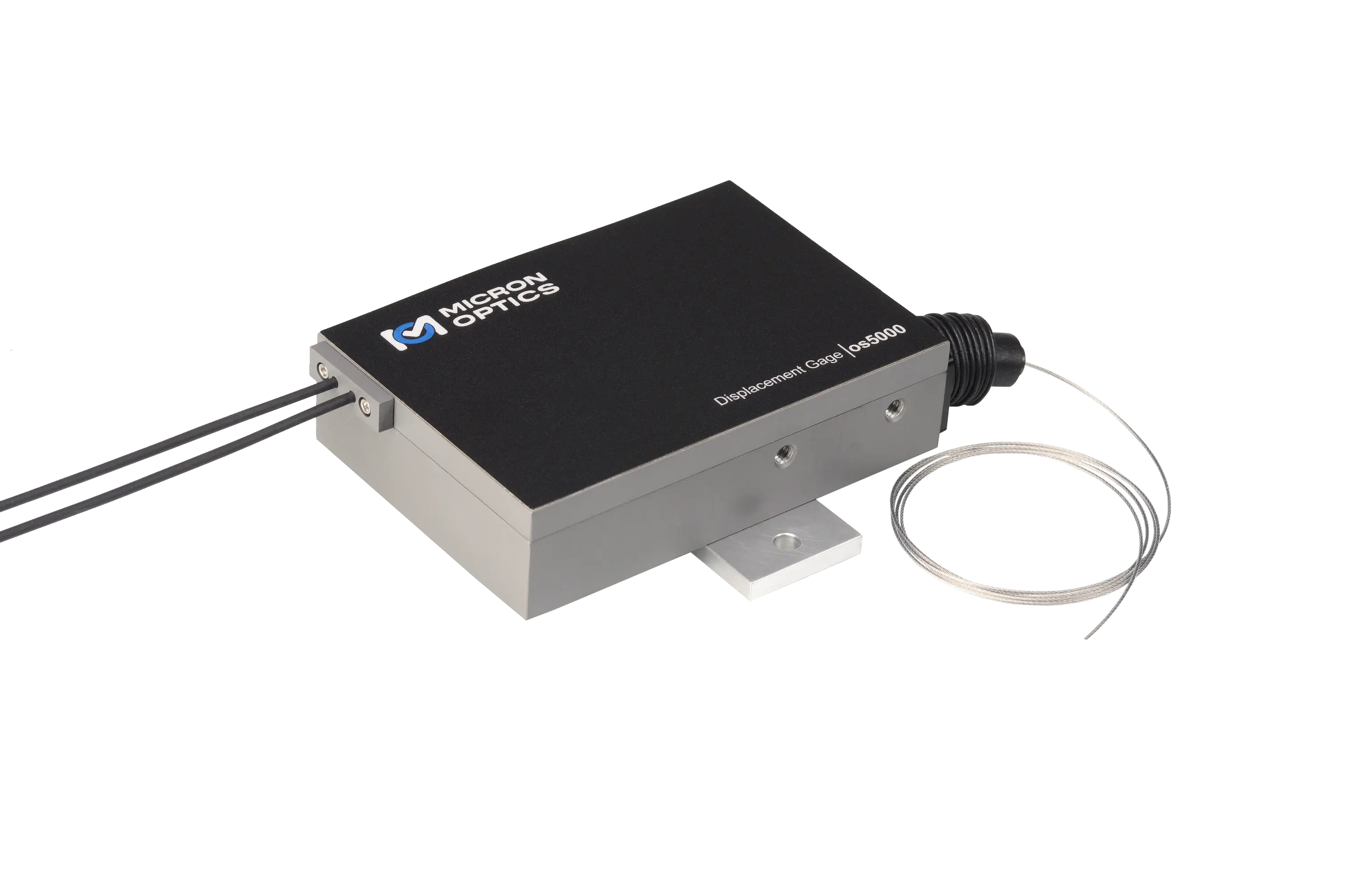
os5000 FBG Displacement Gage for Civil and Geotechnical Structures
FBG-based displacement gage for measuring changes of less than 12 mm between two gage points on civil and geotechnical structures.
- Measurement Range
- 0 - 12 mm
- Resolution
- 0.02% F.S.
- Linearity
- 0.026 mm (.22% F.S.) steady-state
- Operating Temperature Range
- -40 to 80°C
Overview
The Luna os5000 is a fiber Bragg grating (FBG) based displacement gage that measures the displacement between two gage points on a specimen surface. It is intended for small changes of less than 12 mm in civil and geotechnical structures. The gage design allows attachment to various substrates, including metal and concrete.
The two FBG sensors in the os5000 are housed in a hard-coat anodized aluminum enclosure. The enclosure shields them from the elements and allows installation in harsh environments.
The gage can be used alone or in series as part of an FBG sensor array, which may also include strain and temperature gages, accelerometers and other displacement gages. Cables can be joined directly inside the enclosure, so separate junction boxes are not needed. Like other FBG-based sensors, the os5000 is immune to electromagnetic interference (EMI).
Each gage ships with a Sensor Information Sheet that lists the gage factor and calibration coefficients needed to convert wavelength information into engineering units. The ENLIGHT Sensing Software provides a utility to calculate, record, display and transmit data for large sensor networks.
Key Features
- Up to 12 mm measurement range using a 1 mm stainless steel cable
- Rugged aluminum enclosure with IP67 rating, suitable for outdoor installations
- Internal protection of connectors/splices
- Double-ended design supports multiplexing of many sensors on one fiber
- Fully temperature compensated over the entire operating range
- Fast response time, stable measurements, high resolution
- Qualified to same rigorous standards used for comparable electronic gages
- Designed for simple installation in a variety of applications
- Cables can be joined directly inside the enclosure, eliminating separate junction boxes
- EMI immunity
Specifications
| Measurement Range | 0 - 12 mm |
|---|---|
| Resolution |
0.02% F.S.
Full scale, room temperature, measured on calibrated displacement stage using Micron Optics sm130
|
| Linearity |
0.026 mm (.22% F.S.) steady-state
Drift pass criteria < 0.8% FS
|
| Operating Temperature Range | -40 to 80°C |
| Environmental Ingress | Suitable for wet, high humidity environments (IP67) |
| Fatigue Life |
>50x106 cycles @ 30% F.S.
As extracted from the datasheet; presumably >50x10^6 cycles
|
| Dimensions |
See Diagram Below, m
Refer to the os5000 drawing
|
|---|---|
| Weight | 954 g |
| Construction | Anodized Aluminum |
| Lead Cable Length | Customer Specified |
| Lead Cable Type | oc1110, 3 mm Tactical Buffered Cable |
| Mounting | Supplied Mounting Plate (see drawing) |
| Peak Reflectivity (Rmax) | > 70% |
|---|---|
| FWHM (- 3 dB point) | 0.25 nm (± .05 nm) |
| Isolation |
> 15 dB
@ ± 0.4 nm around center wavelength
|
| Part number format |
os5000-wwww/wwww-1xx
Example: os5000-1548/1553-1FC
|
|---|---|
| Standard wavelengths (wwww, +/- 1.5 nm) |
1471/1476, 1482/1487, 1493/1498, 1504/1509, 1515/1520, 1526/1531, 1537/1542, 1548/1533, 1559/1564, 1570/1575, 1581/1586, 1592/1597, 1603/1608, 1614/1619
Bandwidth allocation requires an additional +/- 3nm. The '1548/1533' entry is printed this way; the ordering example uses 1548/1553
|
| Length (1xx) | Standard length is 1 m |
| Termination (1xx) | FC: FC/APC Connector; FS: Fusion Splice |
Specifications are taken from the manufacturer's documentation. See the datasheet for complete and current values.
Applications
- SHM for civil and geotechnical structures
- SHM for energy systems
- Structures (bridges, dams, tunnels, mines, buildings, oil platforms)
- Energy (wind turbines, oil wells, pipelines, nuclear reactors, generators)
- Transportation (railways, trains, roadways, specialty vehicles, cranes)
- Marine vessels (hull, deck, cargo containers)
- Aerospace (airframes, composite structures, wind tunnels, static and dynamic tests)
Included
- Sensor Information Sheet with gage factor and calibration coefficients
- Supplied Mounting Plate
Options & Accessories
| Option | Description |
|---|---|
| FC | FC/APC Connector — Lead termination option |
| FS | Fusion Splice — Lead termination option |
Documents & Resources
Related Products
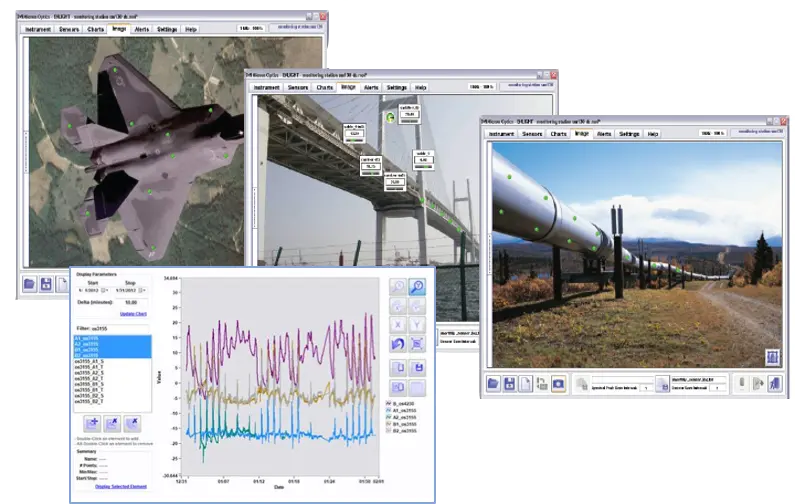
Data acquisition, computation, storage and analysis software for fiber optic sensor networks based on Luna HYPERION interrogators.
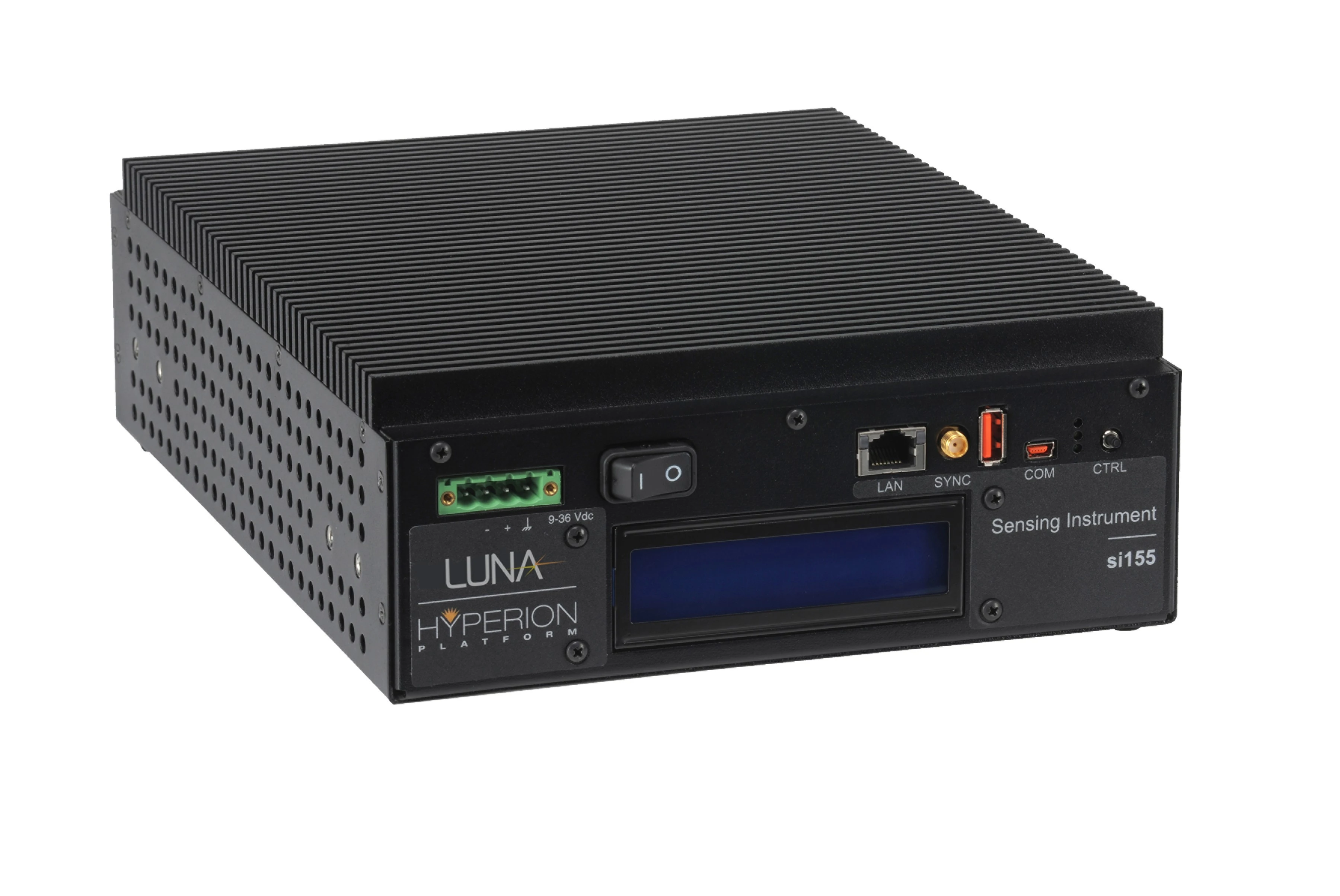
Industrial-grade fan-less optical sensing interrogator with static and dynamic full-spectrum analysis on up to 4 parallel 160 nm wide channels.
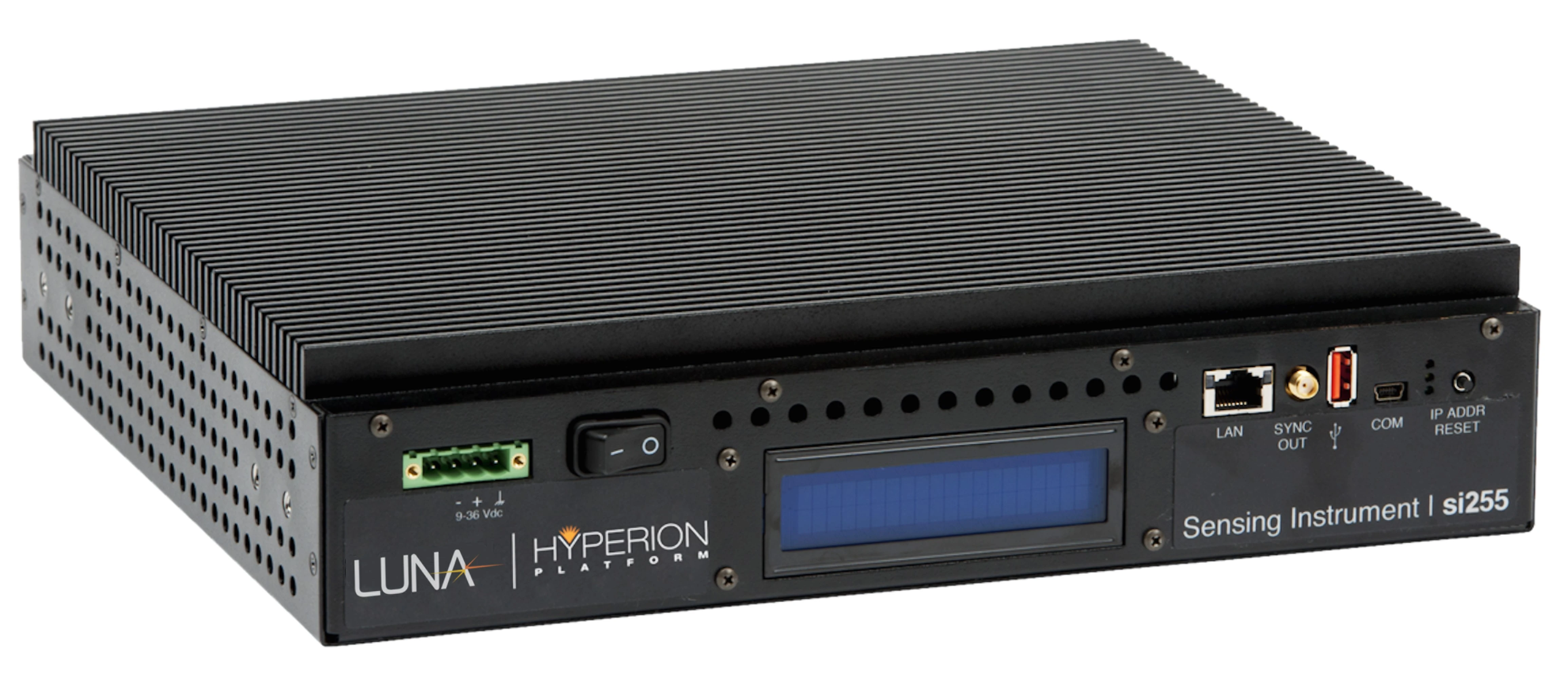
Industrial-grade fan-less interrogator measuring nearly 1000 FBG, LPG, FP and MZ sensors on 16 parallel, 160 nm wide channels.
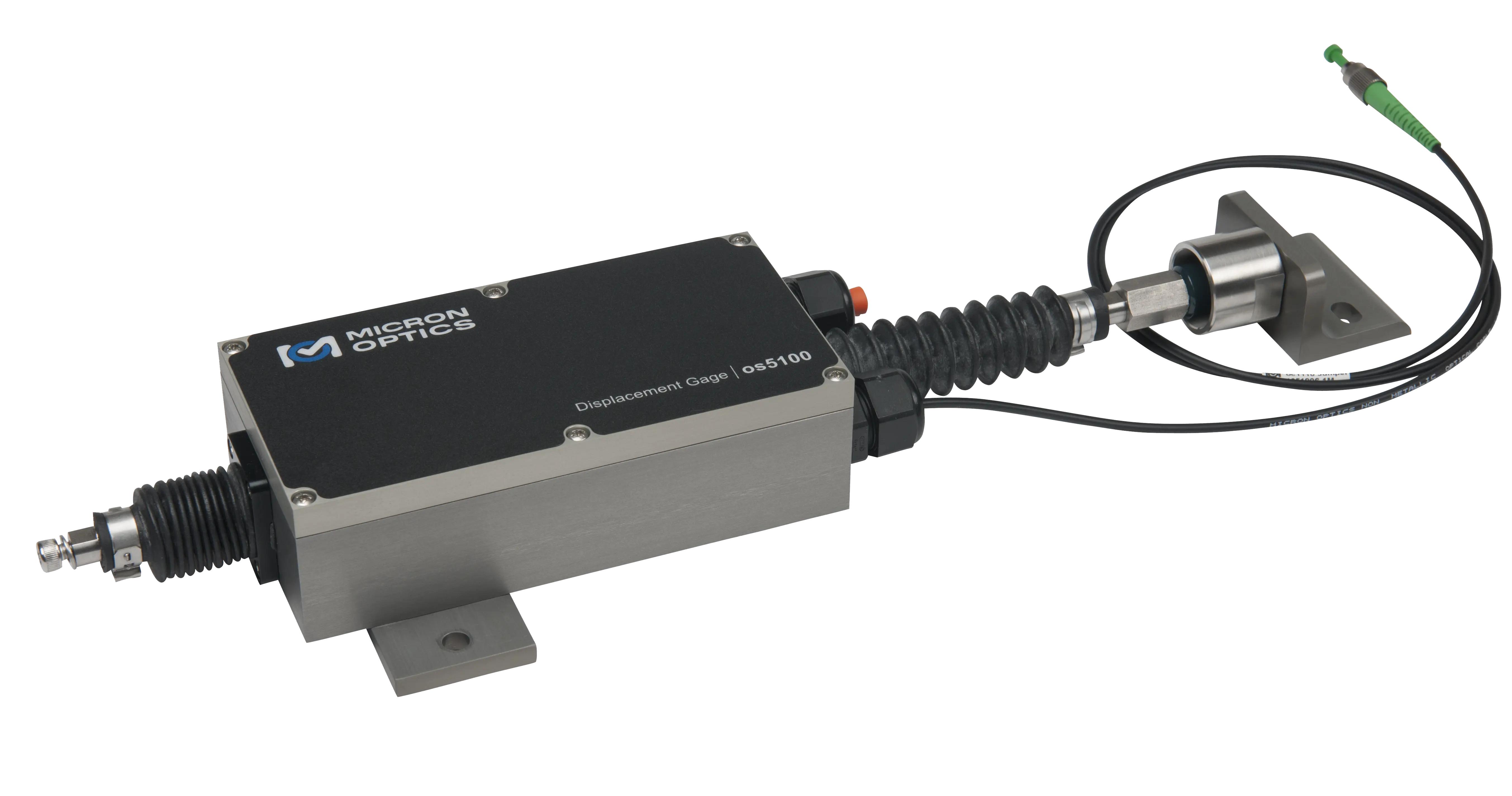
Fiber Bragg grating (FBG) displacement gage for measuring changes of up to 50 mm in civil and geotechnical structures.
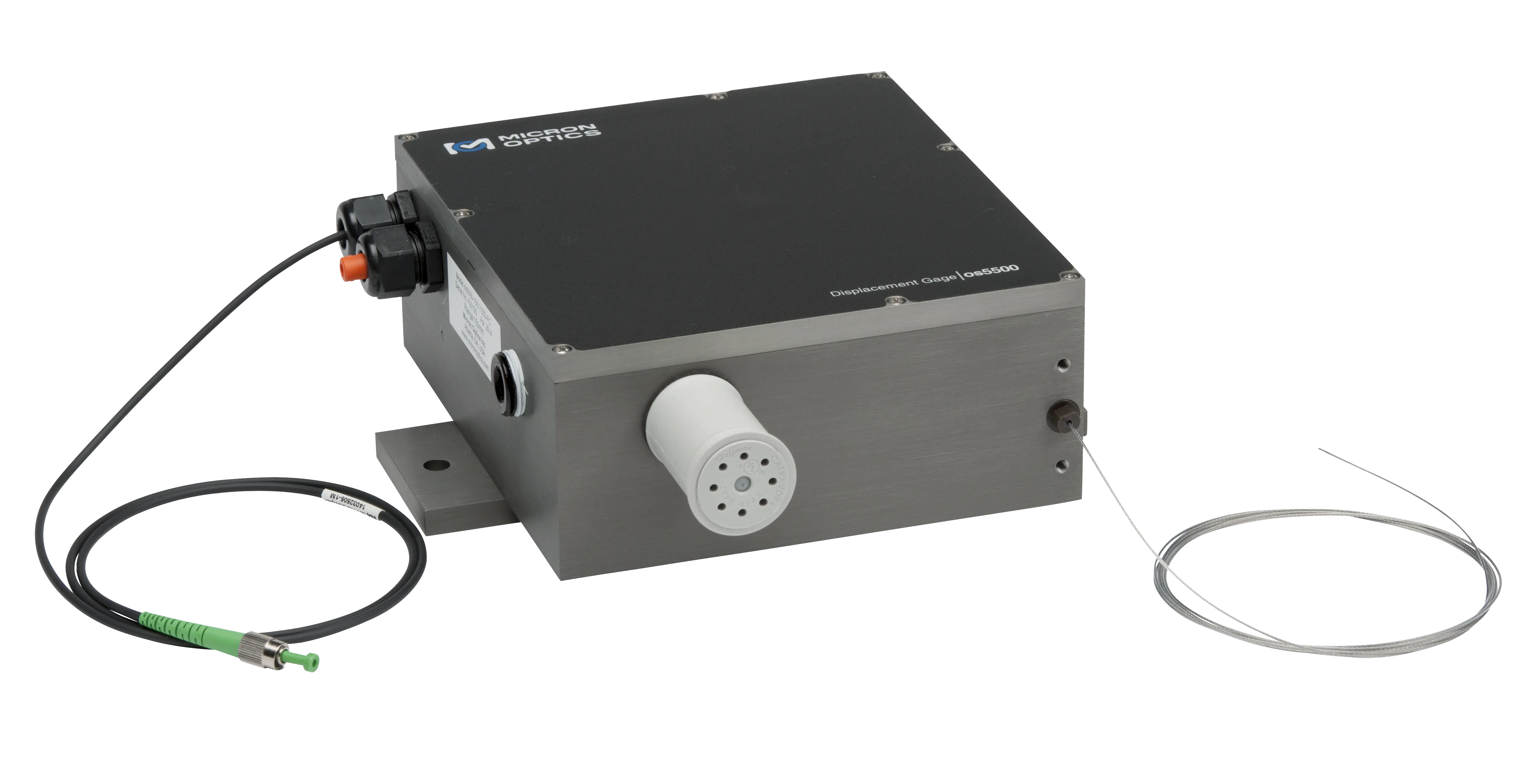
Fiber Bragg grating (FBG) based displacement gage for measuring changes of up to 450 mm in civil and geotechnical structures.