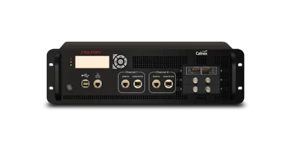
Calnex Sentry Rack Mount Network Synchronization Monitor
Rack mount synchronization monitor for continuous remote monitoring of PTP, NTP and clock signals at Ethernet rates from 100M to 100G.
- PTP (1588) – Main Channels
- Layer 2 Multicast and Layer 3 (UDP/IPv4, UDP/IPv6) Multicast/Unicast
- NTP – Main Channels
- Layer 3 (UDP/IPv4/IPv6) Multicast/Unicast
- PTP (1588) – Virtual Channels
- Layer 3 (UDP/IPv4, UDP/IPv6) Unicast
- NTP – Virtual Channels
- Layer 3 (UDP/IPv4, UDP/IPv6) Unicast
Overview
Calnex Sentry is a rack mount network synchronization monitor for verifying phase, time and frequency synchronization across a whole network. It is designed for large network infrastructure environments such as data centers, where it provides independent, continuous verification that synchronization accuracy is being maintained, and helps identify performance trends before they become issues.
Sentry can be configured with up to two Ethernet measurement channels at rates from 100M to 100G and up to two clock modules for signals such as 1 PPS. One PTP or NTP stream is fully analyzed on each physical channel, with results viewable over VNC. With the multiple measurement option, 2wayTE can be measured on up to 32 additional unicast PTP or NTP streams, giving a total of up to 34 monitored streams. Sentry can act as a pseudo T-TSC to measure upstream network synchronization or as a network monitor measuring live network PDV and TE.
Remote operation and data analysis
The instrument is controlled remotely through Virtual Network Computing (VNC), which gives access to the onboard analytics and graphing, or through an API that automates setup and measurement downloads for integration into network management systems. Measurements run continuously and can be downloaded at short intervals or stored on the instrument for up to 24 hours. Downloaded data can be analyzed in the Calnex Analysis Tool (CAT) and the PTP Field Verifier (PFV), and archived as evidence of compliance with service level agreements or regulations such as MIFID II.
Reference and reliability
Sentry contains a Rubidium reference oscillator and a GNSS receiver; the Rb clock can be disciplined to GNSS or an external 1 PPS source and provides holdover for several hours if GNSS is lost. A hardware watchdog resets the instrument and restarts measurements if it freezes, and redundant hot-swappable power supplies allow one power circuit to be de-energized without interrupting monitoring. Power supply status can be read through the API.
Key Features
- Verify phase, time and frequency synchronization
- PTP accuracy verification and monitoring
- Remotely monitor and diagnose synchronization issues on Ethernet and clock signals
- Two Ethernet ports from 100M to 100G with IPv4 and IPv6
- Monitor up to 34 PTP or NTP streams
- Up to 5 clock inputs from 0.5 Hz to 200 MHz
- Internal high-stability Rubidium oscillator disciplined to GNSS or external 1PPS
- ±75 ns constant TE measurement accuracy with reference to GNSS
- Relative time error between clock inputs rTE ≤ 5 ns
- Setup and data download over API; direct operation over VNC
- Fixed duration or continuous measurements, all measurements simultaneous
- Measurement data stored on the instrument for up to 24 hours
- Measurements include TE, TIE, MTIE, TDEV, 2wayTE, dynamic TE, PDV, FPP and frequency error
- Pass/fail against ITU-T masks and standards-based or vendor-specific limits
- Detailed measurement report in PDF format
- Onboard PTP packet capture and decode of Signaling, Sync, Del-Req, Del-Resp and Announce messages
- Hardware watchdog with automatic reboot and measurement restart
- Redundant hot-swappable power supplies
- Full analysis in Calnex Analysis Tool (CAT) and PTP Field Verifier (PFV)
Specifications
| PTP (1588) – Main Channels | Layer 2 Multicast and Layer 3 (UDP/IPv4, UDP/IPv6) Multicast/Unicast |
|---|---|
| NTP – Main Channels | Layer 3 (UDP/IPv4/IPv6) Multicast/Unicast |
|
PTP (1588) – Virtual Channels
Option 621
|
Layer 3 (UDP/IPv4, UDP/IPv6) Unicast |
|
NTP – Virtual Channels
Option 621
|
Layer 3 (UDP/IPv4, UDP/IPv6) Unicast |
| Measurement Channels |
Maximum of 2 Channels
Each channel can be configured with multiple line rates; only one line rate per channel is active for a measurement
|
| Connectors |
RJ45 for 100/1000 Base-T; SFP/SFP+ for 100M/1G/10G Optical; QSFP28 for 100G Optical; SFP28 for 25G Optical
QSFP28 to SFP28 adapter supplied with 25G option. Optical transceivers not supplied.
|
| Accuracy |
PTP/NTP constant TE measurement accuracy with reference to GNSS ±75 ns
Web page states ±75ns absolute accuracy to UTC; datasheet specifies reference to GNSS
|
| Packet Rate | 128 packets/sec if only main two channels are used decreasing to 1 packet/sec if two Main and 32 Virtual Channels are active |
|
Virtual Channels
Option 621
|
2wayTE can be measured on a total of 32 additional PTP or NTP streams
Requires Option 621; Virtual Channels must be Unicast and differentiated by IP address
|
| Data Capture and Visualization |
Measured data is be downloaded over API in CSV format for further analysis
Virtual Channel time error data is also saved by Sentry for download to the Calnex Analysis Tool (CAT)
|
| Data available over API – Main PTP/NTP Channel | TIE, 2wayTE, Path delay, fwdPDV, revPDV, ESMC |
| Data available over API – Virtual channels | 2wayTE, Path delay, fwdPDV, revPDV |
| Masks / Test Limits | Masks or test limits can be applied to TE, 2wayTE, pktSelected 2wayTE, 2wayTEL, 2wayTEH, TIE, MTIE, and TDEV graphs |
|---|---|
| PRC/SSU/SEC Masks | Masks for G.811/G.812/G.813-clocks (ETSI 300 462-3) |
| Network Masks | According to G.823/G.824/G.8261/G.8261.1/G.8271.1/G.8271.2 |
| Display Modes | TE, 2wayTE, pktSelected 2wayTE, TIE, MTIE, TDEV, Path Delay, PDV, 2wayTEL, 2wayTEH, Distribution of PDV Selected PDV, Floor Packet Percentage, Maximum Average Frequency Error |
| Number of Graphs | Up to 6 graphs of the same type can be over-laid on screen. Color coded. |
| Masks on Screen |
Up to 6 MTIE and TDEV masks according to selected test mode
Pass/Fail result available for each mask
|
|
Pre-defined Signal/Clock Types
Option 610
|
1 pps (PTP Subordinate recovered clock); 8 kHz (frame clock); 64 kHz/64 kb/s (E0/DS0); 1.544 MHz/1.544 Mb/s (T1/DS1 clock/data); 2.048 MHz/2.048 Mb/s (E1 clock/data); 5 MHz/10 MHz (frequency reference); 25 MHz/125 MHz/156.25 MHz (SyncE clock rate); 34 Mb/s (E3), 45 Mb/s (DS3); 155.52 MHz/155 Mb/s (STM-1/STS-3 clock/data) |
|---|---|
|
User-defined Clock Types
Option 610
|
From 0.5 Hz to 200 MHz in 0.5 Hz steps
Symmetrical, unipolar clock signals
|
|
Number of Ports
Option 610
|
2 per module |
|
Connector
Option 610
|
BNC |
|
Impedance
Option 610
|
75 Ω, VSWR <2:1 or 1 MΩ |
|
Voltage Range
Option 610
|
±5.00 V |
|
Sensitivity
Option 610
|
min input voltage 60 mVpp
Signal Check voltages are for indication only
|
|
Signal Type
Option 610
|
Symmetrical pulse (clock signal); Unsymmetrical repetitive pulse (clock signal); HDB3-coded data (data signal); AMI B8ZS, B3ZS (data signal) |
|
Frequency Measurement
Option 610
|
TIE accuracy 1 ns |
|
1 pps Accuracy
Option 610
|
Constant TE measurement accuracy with reference to GNSS ±75 ns |
| Relative Time Error |
rTE ≤ 5ns
Accuracy with which Sentry measures the phase difference between any two clock inputs; web page states ±5ns relative time accuracy between any clock and PTP inputs
|
| Reference Clock | Built-in Rubidium reference |
|---|---|
| Output Frequency Accuracy |
1 x 10⁻⁹
7 mins to warmup
|
| Ageing (1 day) | <1 x 10-12 |
| Ageing (1 year) | <5 x 10⁻¹⁰ |
| Built-in GNSS Module | 12 channels, TRAIM GNSS receiver, high sensitivity. GPS, GLONAS, Beidou, Galileo. |
|---|---|
| Time Accuracy | ±15 ns at 1σ after 24 hours lock |
| Frequency Accuracy | 2 x 10 - 12 averaged over 24 hours |
| GNSS Disciplining Modes |
Always disciplining, always in holdover, disciplining only between measurements
Requires 6 hours disciplining if disconnected from GNSS for <1 week; 12 hours if >1 week. Requires 1 hour disciplining if using Cs quality 1 pps (from any state).
|
| External 1 pps Timing Input – Voltage Range | 0 V to 0.8 V (Low), 2 V to 3.3 V (High) into 50 Ω |
|---|---|
| External 1 pps Timing Input – Required Accuracy | ±100 ns to UTC |
| GNSS Antenna Input | type N connector |
| GNSS DC-feed | +5 V on center pin to active GNSS antenna |
| Reference Frequency | 10 MHz sine-wave |
|---|---|
| Output Levels | 1 Vrms in 50 Ω |
| Impedance | Approx. 50 Ω |
| 1 pps Output Source | Internal Rubidium oscillator |
| 1 pps Output Logic Levels | TTL levels in 50 Ω |
| USB Host Port Connector | Std USB type A |
|---|---|
| USB Maximum Supply Current | 400 mA |
| USB Version | 2.0 |
| Ethernet Communication Port | RJ45, 10/100/1000 Base-T |
| Ethernet Protocol | HTTP, HTTPS, DHCP or fixed IP (IPv4 or IPv6), FTP, VNC |
| Data Storage | Internal: Up to 32G; External: USB memory stick |
| Operating Temperature | 0°C to 40°C |
|---|---|
| Storage | Temperature from 0 to 50°C and humidity up to 90% non-condensing |
| Safety | EN61010:2010 +A1:2019 |
| EMC | EN61326-1:2021 |
| Line Voltage | 100 to 240 Vac ± 10%, 50 to 60 Hz ± 3 Hz |
|---|---|
| Instrument Power Consumption |
<100 W
Instrument will operate on one power supply but it is recommended that both are used
|
| Dimensions | 3U cabinet designed for 19” rack. Depth 17.3” (439 mm) |
|---|---|
| Weight | 8.4 kg (max.) |
Specifications are taken from the manufacturer's documentation. See the datasheet for complete and current values.
Applications
- Data center synchronization monitoring
- Telecom network synchronization monitoring
- Detection of rogue time sources
- Comparison of time domains in trading venues
- Remote measurement of unicast boundary clocks
- O-RAN DU rTE validation
- 5G network synchronization
- MIFID II timing compliance verification
- SLA evidence for timing provided to tenants
Included
- Calnex Analysis Tool (CAT)
- PTP Field Verifier Tool (PFV)
- User manual on USB
- Line power cord
- 1-year warranty and support
Options & Accessories
| Option | Description |
|---|---|
| 610 | Clock module 1PPS/E1/T1 — Any clock from 0.5 Hz up to 200 MHz with 0.5 Hz step (maximum two per instrument) |
| 615 | 100M/1G packet port (PTP/NTP) — Can order maximum of 2 x Opt. 615 (maximum two – Opt. 615 and/or Opt. 616 per instrument) |
| 616 | 100M/1G/10G packet port (PTP/NTP) — Can order maximum of 2 x Opt. 616 (maximum two – Opt. 615 and/or 616 per instrument) |
| 618 | 100G Interface — Ordered at same time as Sentry mainframe or SW upgrade enabling second 100G port |
| 622 | 25G Interface — Ordered at same time as Sentry mainframe or SW upgrade enabling second 25G port; QSFP28 to SFP28 adapter supplied |
| 620 | PTP and NTP PDV measurement software — One license per instrument |
| 621 | 32 additional virtual NTP/PTP measurements |
| 812 | One year extension of product warranty |
| 813 | Two years extension of product warranty |
Documents & Resources
Related Products
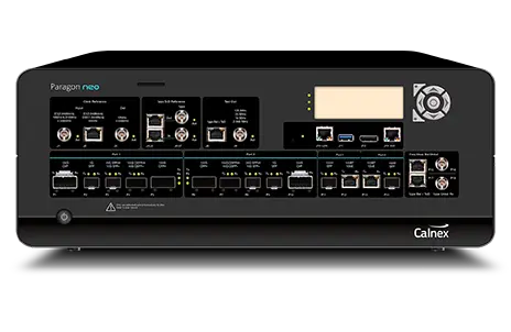
PTP and SyncE test platform with sub-ns Time Error accuracy, up to 100GbE, or 400GbE with the Paragon neo-A PAM4 version
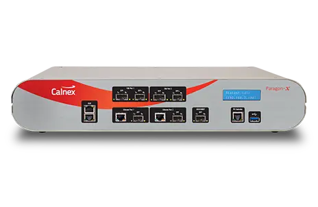
One-box tester for PTP (1588), SyncE, NTP, CES and Ethernet OAM synchronization at speeds up to 10GbE with 5 ns accuracy.
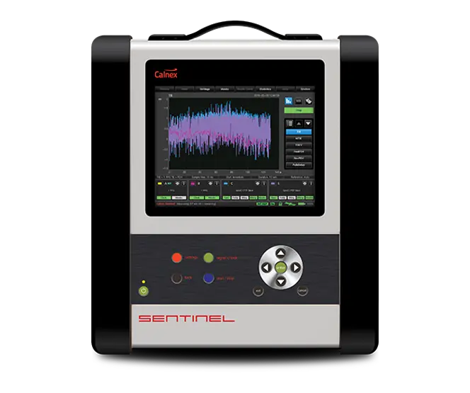
Portable sync analyzer that verifies phase, time and frequency synchronization over PTP, NTP, SyncE, 1PPS and 4G/5G Over-The-Air at up to 100G.