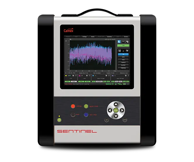
Calnex Sentinel Portable Synchronization Tester for PTP, NTP, SyncE, 1PPS and 4G/5G OTA
Portable sync analyzer that verifies phase, time and frequency synchronization over PTP, NTP, SyncE, 1PPS and 4G/5G Over-The-Air at up to 100G.
- Test modes
- Masks or test limits can be applied to TE, 2wayTE, pktSelected 2wayTE, 2wayTEL, 2wayTEH, TIE, MTIE, and TDEV graphs
- PRC/SSU/SEC masks
- Masks for G.811/G.812/G.813-clocks (ETSI 300 462-3)
- Network masks
- According to G.823/G.824/G.8261/G.8261.1/G.8271.1/G.8271.2
- SyncE masks
- According to G.8261, G.8262
Overview
The Calnex Sentinel is a dedicated synchronization tester for verifying phase, time and frequency synchronization. It is used to monitor performance and diagnose synchronization issues on 3G/4G/5G mobile, data center, financial, power and other telecoms networks. Sentinel captures all data simultaneously, so timing performance can be correlated at different points in the network, even between different timing architectures.
Measurements
The instrument measures PTP, NTP and SyncE (IPv4/IPv6) on packet ports from 100M to 100G, as well as 1PPS and clock signals. It can operate as a pseudo T-TSC to measure upstream network synchronization or as a network monitor measuring live network PDV and time error. Metrics include Time Error, TIE, MTIE, TDEV, 2wayTE, packet-selected 2wayTE, PDV, Floor Packet Percentage, frequency error, SyncE wander and ESMC quality levels, assessed against ITU-T masks and limits.
Over-The-Air testing
An optional OTA module measures time error between 4G eNodeBs or 5G gNodeBs and UTC without a physical connection to the network, which is useful where small cells lack a 1PPS output. It supports FDD and TDD and absolute and relative virtual 1PPS measurements. With the battery option, OTA measurements can be made in the field without external power.
Reference and holdover
Sentinel includes a built-in GNSS receiver and a rubidium reference clock. Once disciplined, the Rb clock provides holdover so that accurate measurements can be made away from a GNSS or 1PPS reference, for example when moving around a data center.
Analysis
Live metrics and real-time graphs are shown during measurement. Built-in packet capture and the PTP Field Verifier (PFV) check protocol conformance, the Calnex Analysis Tool (CAT) provides detailed metric analysis and PDF reporting, and captured PDV data can be replayed on Calnex Paragon instruments.
Key Features
- Verifies phase, time and frequency synchronization
- PTP, NTP and SyncE (IPv4/IPv6) measurements
- 1PPS and clock signal measurements
- Over-The-Air (OTA) time error measurement for 4G and 5G, FDD or TDD
- Absolute and relative virtual 1PPS OTA measurements
- Multiple clock and packet measurements simultaneously
- G.8265.1/G.8275.1/G.8275.2 testing with profiles and metrics
- PTP Pseudo Subordinate PDV/2wayTE to ITU-T specifications
- NTP Pseudo Client PDV/2wayTE performance
- SyncE wander and ESMC measurements
- PTP protocol check and built-in packet capture
- 25/100G interfaces
- Battery operation for OTA measurements
- Long-term PTP TE measurements at 1G/10G/25G/100G with or without GNSS
- Embedded GNSS receiver and high-stability rubidium (Rb) clock
- Live metrics calculated and displayed in real time
- Detailed measurement report in PDF
- PTP Field Verification (PFV) to check conformance
- Calnex Analysis Tool (CAT) for full suite of metrics
- Auto discovery of signals
- Built-in industry-standard masks and PTP profiles
- Remote operation via VNC or API
- Captured PDV data can be replayed on Calnex Paragon
Specifications
| Test modes | Masks or test limits can be applied to TE, 2wayTE, pktSelected 2wayTE, 2wayTEL, 2wayTEH, TIE, MTIE, and TDEV graphs |
|---|---|
| PRC/SSU/SEC masks | Masks for G.811/G.812/G.813-clocks (ETSI 300 462-3) |
| Network masks | According to G.823/G.824/G.8261/G.8261.1/G.8271.1/G.8271.2 |
| SyncE masks | According to G.8261, G.8262 |
| ANSI-standard masks | DS1 and OC-N masks |
| Display modes | TE, 2wayTE, pktSelected 2wayTE, TIE, MTIE, TDEV, Path Delay, PDV, 2wayTEL, 2wayTEH, Distribution of PDV Selected PDV, Floor Packet Percentage, Maximum Average Frequency Error |
| Number of graphs | Up to 6 graphs of the same type can be over-laid on screen. Color coded. |
| Masks on screen |
Up to 6 MTIE and TDEV masks according to selected test mode
Pass/Fail result available for each mask
|
|
Pre-defined signal/clock
Option 610
|
1PPS (PTP Subordinate recovered clock); 8 kHz (frame clock); 64 kHz/64 kb/s (E0/DS0); 1.544 MHz/1.544 Mb/s (T1/DS1 clock/data); 2.048 MHz/2.048 Mb/s (E1 clock/data); 5 MHz/10 MHz (frequency reference); 25 MHz/125 MHz/156.25 MHz (SyncE clock rate); 34 Mb/s (E3), 45 Mb/s (DS3); 155.52 MHz/155 Mb/s (STM-1/STS-3 clock/data) |
|---|---|
|
User-defined clock types
Option 610
|
From 0.5 Hz to 200 MHz in 0.5 Hz steps
Symmetrical, unipolar clock signals
|
|
Number of ports
Option 610
|
2 per module |
|
Connector
Option 610
|
BNC |
|
Impedance
Option 610
|
75 Ω, VSWR <2:1 or 1 MΩ |
|
Voltage range
Option 610
|
±5.00 V |
|
Sensitivity
Option 610
|
min input voltage 60 mVpp
Signal Check voltages are for indication only
|
|
Signal type
Option 610
|
Symmetrical pulse (clock signal); Unsymmetrical repetitive pulse (clock signal); HDB3-coded data (data signal); AMI B8ZS, B3ZS (data signal) |
|
Frequency measurement
Option 610
|
TIE accuracy 1 ns |
|
1PPS constant TE measurement accuracy
Option 610
|
±75 ns
With reference to GNSS
|
| Relative time error |
±5 ns
Accuracy with which Sentinel measures the phase difference between any two clock inputs
|
| Synchronous Ethernet | SyncE clock measurement; Conformance to G.8261 masks (MTIE/TDEV); Extract and graph ESMC message (SSM); Generate and change ESMC |
|---|---|
| PTP (1588) and NTP measurements | Network 2-way TE, Forward (Sync) PDV, Reverse (DelReq) PDV and Network Delay; Raw PDV (vs time and distribution graphs); Selected Packet PDV (vs time and distribution graphs); Cluster/band packet selection |
| Operating modes | Pseudo-Subordinate Clock Mode or Monitor Mode |
| Timestamp resolution | 1 ns resolution timestamp |
| PDV replay | Captured PDVs can be replayed on Calnex Paragon-X for troubleshooting |
| PTP (1588) transport | Layer 2 Multicast and Layer 3 (UDP/IPv4, UDP/IPv6) Multicast/Unicast |
| NTP transport | Layer 3 (UDP/IPv4/IPv6) Unicast |
| Number of ports | Maximum of 2 |
| Connectors |
RJ45 for 100/1000 Base-T, SFP/SFP+ for 100M/1G/10G Optical, QSFP28 for 100G Optical, SFP28 for 25G Optical
QSFP28 to SFP28 adapter supplied; optical transceivers not supplied
|
| PTP/NTP constant TE measurement accuracy |
±75 ns
With reference to GNSS
|
|
Measurement accuracy
Option 705
|
±100 ns |
|---|---|
|
Maximum input power
Option 705
|
–20 dBm |
|
Operating frequencies
Option 705
|
Up to 6 GHz |
|
NR and LTE bands
Option 705
|
TDD and FDD |
| Reference clock | Built-in Rubidium reference or external reference input 1 MHz, 5 MHz or 10 MHz |
|---|---|
| Internal data storage | Up to 32G |
| External data storage | USB memory stick |
| Start/Stop | Via START/STOP key |
| Signal check parameters | Signal type (Clock, Data or Unknown); Frequency (for clock signals); Pulse width (for data signals) |
| Display | Color TFT, 8.4", 800 x 600 pixels, resistive touchscreen |
| Output frequency accuracy |
1 x 10⁻⁹
7 mins to warmup
|
|---|---|
| Ageing (1 day) | <1 x 10-12 |
| Ageing (1 year) | <5 x 10⁻¹⁰ |
| Built-in GNSS module |
12 channels, GPS L1, Galileo E1, GLONASS G1 and BeiDou B1 bands
Not compatible with B1C
|
| Time accuracy |
±15 ns at 1σ after 24 hours lock
GNSS-disciplined
|
| Frequency accuracy |
2 x 10-12 averaged over 24 hours
GNSS-disciplined
|
| GNSS disciplining modes |
Always disciplining, always in holdover, disciplining only between measurements
Requires 6 hours disciplining if disconnected from GNSS for <1 week; 12 hours if >1 week. Requires 1 hour disciplining if using Cs quality 1PPS (from any state).
|
| Frequency reference input (std) | Input Frequency: 10 MHz, 5 MHz. Voltage Range: 0.1 Vrms to 5 Vrms. Impedance: Approx. 50 Ω. |
|---|---|
| External 1PPS timing input | Voltage Range: 0 V to 0.8 V (Low), 2 V to 3.3 V (High) into 50 Ω. Required Accuracy: ±100 ns to UTC |
| GNSS timing reference | Antenna Input: N-type connector. DC-feed: +5 V on center pin to active GNSS antenna. |
| Reference frequency output | Reference Frequency: 10 MHz sine-wave. Output Levels: 1 Vrms in 50 Ω. Impedance: Approx. 50 Ω. |
| 1PPS output | Voltage Range: 0 V to 0.8 V (Low), 2 V to 3.3 V (High) into 50 Ω. Source: Internal Rubidium oscillator |
| E1/T1 output | Output Logic Levels: TTL levels in 50 Ω. Connector: Clock: BNC, Data: Isolated BNC. Frequency: 2.048/1.544 MHz, 2.048/1.544 Mb/s. Output Level: Accurate to G.703 ±1.2 V ±10% in 75 Ω |
| USB device port | Connector: Std USB type B. USB Version: 2.0 |
|---|---|
| USB host port | Connector: Std USB type A. Maximum Supply Current: 400 mA. USB Version: 2.0 |
|
USB charging port
Option 631
|
Connector USB type C. Supports 20 V, 5 A profile.
Input port only for charging Opt. 631 internal battery
|
| LAN/management port | Communication Port: RJ45, 10/100 Base-T. Protocol: DHCP, FTP, web-based GUI (http/https) with authentication if required, WebDav. Supports VLAN |
| Remote operation | Remote operation via web-based GUI |
| Event log | On screen log of measurement start/stop, duration, alarms, loss of data, loss of communication link, etc. Log can be saved as text file. |
| Report generation | Printable, custom-designed measurement report in pdf format |
| Security | Password secured access |
| Operating temperature |
0°C to 40°C
30°C when charging Rb backup-battery
|
|---|---|
| Storage | Temperature from 0 to 50°C and Humidity up to 90% non-condensing |
| Safety | EN 61010-1: 2010 |
| EMC | EN 61326: 2013 |
| Power supply | Line Voltage: 100 to 240 Vrms ±10%, 50 Hz to 60 Hz, <100 W |
| Construction | Fold-out stand. Ruggedized casing. |
|---|---|
| Dimensions (w x h x d) | 320 x 388 x 126 mm (12.6" x 15.3" x 5") |
| Weight |
Net <7 kg (15 lb); Shipping with transport case <16 kg (35 lb)
Weights are approximations based on varying configurations
|
Specifications are taken from the manufacturer's documentation. See the datasheet for complete and current values.
Applications
- 3G/4G/5G mobile network synchronization
- Small cell deployment testing
- O-RAN synchronization conformance
- Data center PTP and NTP synchronization
- Financial network timing
- Power network timing
- Telecom network synchronization monitoring
- Network deployment, troubleshooting and maintenance
Included
- Calnex Analysis Tool (CAT)
- GNSS antenna
- Antenna cable (20 m)
- Hard transport case
- User manual on USB
- Line power cord
- 1-year warranty and support
- QSFP28 to SFP28 adapter
Options & Accessories
| Option | Description |
|---|---|
| Option 610 | Clock module 1PPS/E1/T1 — Any clock from 0.5 Hz up to 200 MHz with 0.5 Hz step (maximum two per instrument) |
| Option 615 | 100M/1G packet port (PTP/NTP/SyncE) — Includes SyncE/ESMC analysis for 100M/1G optical and electrical rates. Maximum two Option 615 and/or Option 616 per instrument. |
| Option 616 | 100M/1G/10G packet port (PTP/NTP/SyncE) — Includes SyncE/ESMC analysis for 100M/1G/10G optical and electrical rates. Maximum two Option 615 and/or Option 616 per instrument. |
| Option 618 | 100G interface — Ordered at same time as Sentinel mainframe or software upgrade enabling second 100G port |
| Option 622 | 25G interface — Ordered at same time as Sentinel mainframe or software upgrade enabling second 25G port |
| Option 705 | Over-the-Air (OTA) Time Error measurement module — Maximum one per instrument |
| Option 620 | PTP and NTP PDV measurement software — One license per instrument |
| Option 623 | Return to factory upgrade of Sentinel with serial no. beginning 400 — Required when upgrading Sentinel with 25G and/or 100G interfaces. Options 618 and/or 622 must be ordered at the same time. |
| Option 631 | Battery Powered Operation — Transport Mode to maintain Rb accuracy in holdover during transportation; uninterruptible power supply maintains operation if external power is interrupted; full operation under battery power without external supply. |
| Option 812 | One year extension of product warranty |
| Option 813 | Two years extension of product warranty |
| Option 133 | External 1PPS/ToD/Frequency Converter accessory |
| Option 511 | Carry-on bag |
Documents & Resources
Related Products
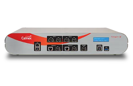
One-box tester for PTP (1588), SyncE, NTP, CES and Ethernet OAM synchronization at speeds up to 10GbE with 5 ns accuracy.
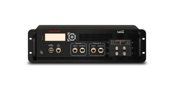
Rack mount synchronization monitor for continuous remote monitoring of PTP, NTP and clock signals at Ethernet rates from 100M to 100G.