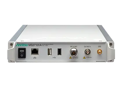
Anritsu MS27101A Remote Spectrum Monitor, 9 kHz to 6 GHz Half-Rack Indoor Spectrum Monitor
Half-rack, 1U indoor remote spectrum monitor covering 9 kHz to 6 GHz with sweep speeds up to 24 GHz/s and an integrated web server.
- Frequency Range
- 9 kHz to 6 GHz (tunable to 0 Hz)
- Tuning Resolution
- 1 Hz
- Frequency Reference Accuracy
- ±1.5 ppm (25 °C ± 25 °C) ±1.0 ppm/year aging
- Frequency Reference Accuracy (GPS on)
- < ±50 ppb
Overview
The Anritsu MS27101A Remote Spectrum Monitor is a small receiver housed in a ½ rack enclosure with 1U height, designed exclusively for indoor applications. It is used to mitigate interference problems and to identify illegal or unlicensed signal activity, and can be deployed hundreds or thousands of kilometers from the control center. An optional bracket kit allows rack mounting, including combining two monitors in a standard rack-mount cage. Anritsu also offers the outdoor IP67-rated MS27102A and the multi-port MS27103A in the same family.
The monitor covers 9 kHz to 6 GHz with sweep rates up to 24 GHz/s and a 20 MHz instantaneous FFT bandwidth, allowing capture of periodic, transient and short bursty signals. A typical use is real-time capture of the entire FM radio band for later playback and analysis. Low spurious levels allow low-level signals to be distinguished from signals generated by the monitor itself.
Remote operation
The MS27101A is designed for unattended field deployment, with remote power cycling, automated system recovery, a hardware watchdog timer and remote firmware updates. A protected "Golden" firmware image is stored on each unit and is used to restore operation if the firmware becomes corrupted or a downloaded update fails validation.
Connectivity and control
Communication is via the Gigabit Ethernet port, using DHCP or a static IP address (shipped default 10.0.0.2); a USB cellular modem can also be used. An integrated web server allows the instrument to be viewed and controlled from any browser, and all commands are available as SCPI. An integrated GPS receiver provides location and time synchronization, and IQ data can be captured in block or streaming mode with time stamps for time difference of arrival (TDOA) applications.
Software
The optional Vision MX280001A software (Windows 7/8/10/11) provides automated monitoring, spectrum history storage, alarms and geo-location of interferers using three or more probes. IQ Signal Master MX280005A Vector Signal Analysis Software, enabled by option 0128, provides post-processing, modulation quality measurements and playback of captured IQ data.
Key Features
- 9 kHz to 6 GHz frequency range
- Sweep speed up to 24 GHz/s
- 20 MHz instantaneous FFT bandwidth
- Integrated web server to view, control and conduct measurements via web browser
- Hardware watchdog timer for long-term stability of remotely deployed monitors
- Remote firmware updates with Golden Image recovery
- Low spur levels for accurate signal discovery
- Low power consumption <11 watts
- Integrated GPS receiver for location and time synchronization
- Gigabit Ethernet
- IQ block mode and streaming with time stamping for TDOA applications
- Remote control via SCPI commands
- Linux operating system
- Measurements: occupied bandwidth, channel power
- Interference analysis: spectrogram and signal strength
- Optional Vision software for automated measurements, alarms and geo-locating signal sources
Specifications
| Frequency Range | 9 kHz to 6 GHz (tunable to 0 Hz) |
|---|---|
| Tuning Resolution | 1 Hz |
| Frequency Reference Accuracy | ±1.5 ppm (25 °C ± 25 °C) ±1.0 ppm/year aging |
| Frequency Reference Accuracy (GPS on) |
< ±50 ppb
With GPS on
|
| Frequency Span | 10 Hz to 6 GHz |
| Sweep Speed, 10 kHz RBW |
5 GHz/s
Typical (full span FFT mode)
|
| Sweep Speed, 30 kHz RBW |
12 GHz/s
Typical (full span FFT mode)
|
| Sweep Speed, 3 MHz RBW |
24 GHz/s
Typical (full span FFT mode)
|
| Resolution Bandwidth (RBW) |
10 Hz to 3 MHz in 1–3 sequence
–3 dB bandwidth
|
|---|---|
| Video Bandwidth (VBW) |
10 Hz to 3 MHz in 1–3 sequence
–3 dB bandwidth; auto or manually selectable
|
| IF / FFT Bandwidth |
20 MHz
Instantaneous FFT bandwidth
|
| SSB Phase Noise @ 1 GHz, 10 kHz offset |
(–98 dBc/Hz)
Typical. Product brochure states –99 dBc/Hz @ 10 kHz offset at 1 GHz
|
|---|---|
| SSB Phase Noise @ 1 GHz, 100 kHz offset |
(–98 dBc/Hz)
Typical
|
| Dynamic Range |
(> 106 dB at 2.4 GHz), 2/3 (TOI-DANL) in 1 Hz RBW
Typical
|
|---|---|
| Measurement Range | DANL to Maximum Continuous Input |
| Reference Level Range | –150 dBm to +30 dBm |
| Attenuator Range | 0 dB to 50 dB in 5 dB steps |
| Amplitude Units | Log Scale Modes: dBm, dBµV |
| Amplitude Accuracy, 9 kHz to 6.0 GHz |
± 2.5 dB
Attenuation ≤ 40 dB, preamp off for frequencies less than 100 kHz
|
| VSWR | < 2.5:1 typical |
| DANL, preamp off, 10 MHz to 3.3 GHz |
–145 dBm max, –150 dBm typical
RBW normalized to 1 Hz, 0 dB attenuation, reference level –20 dBm
|
|---|---|
| DANL, preamp off, > 3.3 GHz to 4.1 GHz |
–140 dBm max, –145 dBm typical
RBW normalized to 1 Hz, 0 dB attenuation, reference level –20 dBm
|
| DANL, preamp off, > 4.1 GHz to 5 GHz |
–138 dBm max, –143 dBm typical
RBW normalized to 1 Hz, 0 dB attenuation, reference level –20 dBm
|
| DANL, preamp off, > 5 GHz to 6 GHz |
–128 dBm max, –136 dBm typical
RBW normalized to 1 Hz, 0 dB attenuation, reference level –20 dBm
|
| DANL, preamp on, 10 MHz to 3.3 GHz |
–162 dBm max, –165 dBm typical
RBW normalized to 1 Hz, 0 dB attenuation, reference level –50 dBm
|
| DANL, preamp on, > 3.3 GHz to 4.1 GHz |
–159 dBm max, –162 dBm typical
RBW normalized to 1 Hz, 0 dB attenuation, reference level –50 dBm
|
| DANL, preamp on, > 4.1 GHz to 5 GHz |
–156 dBm max, –160 dBm typical
RBW normalized to 1 Hz, 0 dB attenuation, reference level –50 dBm
|
| DANL, preamp on, > 5 GHz to 6 GHz |
–146 dBm max, –154 dBm typical
RBW normalized to 1 Hz, 0 dB attenuation, reference level –50 dBm
|
| Residual Spurious, preamp off |
(< –80 dBm)
Typical; RF input terminated, 0 dB input attenuation, > 10 MHz
|
|---|---|
| Residual Spurious, preamp on |
(< –95 dBm)
Typical; RF input terminated, 0 dB input attenuation, > 10 MHz
|
| Residual Spurious, preamp on, 16 MHz to 18 MHz |
(< –88 dBm)
Typical; RF input terminated, 0 dB input attenuation
|
| Input-Related Spurious |
< –60 dBc
0 dB attenuation, –30 dBm input, carrier offset > 5 MHz
|
| Second Harmonic Distortion, 50 MHz |
(–50 dBc)
Typical; 0 dB attenuation, –30 dBm input
|
| Second Harmonic Distortion, > 50 MHz to 200 MHz |
< –60 dBc
Typical; 0 dB attenuation, –30 dBm input
|
| Second Harmonic Distortion, > 200 MHz to 3000 MHz |
< –60 dBc
Typical; 0 dB attenuation, –30 dBm input
|
| Third-Order Intercept (TOI), 800 MHz |
(+7 dBm)
Typical; preamp off, –20 dBm tones 100 kHz apart, 0 dB attenuation, reference level –20 dBm
|
| Third-Order Intercept (TOI), 2400 MHz |
(+17 dBm)
Typical; preamp off, –20 dBm tones 100 kHz apart, 0 dB attenuation, reference level –20 dBm
|
| Third-Order Intercept (TOI), 200 to 2200 MHz |
(+10 dBm)
Typical; preamp off, –20 dBm tones 100 kHz apart, 0 dB attenuation, reference level –20 dBm
|
| Third-Order Intercept (TOI), > 2.2 GHz to 5.0 GHz |
(+8 dBm)
Typical; preamp off, –20 dBm tones 100 kHz apart, 0 dB attenuation, reference level –20 dBm
|
| Third-Order Intercept (TOI), > 5.0 GHz to 6.0 GHz |
(+14 dBm)
Typical; preamp off, –20 dBm tones 100 kHz apart, 0 dB attenuation, reference level –20 dBm
|
| 100 MHz to 6 GHz, ≥ 10 dB attenuation |
+30 dBm, ±50 VDC
For lower frequencies, derate maximum continuous input by 6 dB per decade
|
|---|---|
| 300 kHz to 6 GHz, < 10 dB attenuation |
+10 dBm, ±50 VDC
For lower frequencies, derate maximum continuous input by 6 dB per decade
|
| 9 kHz to 6 GHz, preamp on | –10 dBm, ±50 VDC |
| Data Types | I/Q time series: 8, 10, 16 or 24 bit resolution; Spectrum trace: 100 to 4000 points |
|---|---|
| Data Transfer Modes | I/Q time series or spectrum trace in streaming or block mode |
| I/Q Data Streaming Rate | Gapless on 100Base-T network, Up to 2.6 MHz signal bandwidth |
| I/Q Data Time Stamp Resolution | 8.7 ns |
| I/Q Recording Time, 20 MHz signal bandwidth |
1.3 s (24 bits), 2.5 s (16 bits), 3.8 s (10 bits), 5 s (8 bits)
Typical; output data rate 76.25 / 3 MSPS
|
| I/Q Recording Time, 1.33 kHz signal bandwidth |
4.66 h (24 bits), 9.33 h (16 bits), 13.99 h (10 bits), 18.65 h (8 bits)
Typical; output data rate 76.25 / 40000 MSPS
|
| System Status | Temperature, Serial Number, Firmware Version, Options Installed, Self Test, Application Self Test, GPS |
|---|---|
| System Options | Name, Date and Time, Reset (Factory Defaults, Master Reset, Update Firmware) |
| Directory Management | Sort Method (Name/Type/Date), Ascend/Descend, Internal/USB, Copy |
| Internal Trace/Setup Memory | 4 GB internal memory available for storing files |
| Mode Switching | Automatically stores/recalls most recently used setup parameters in the mode |
| RF In | Type N, female port, 50 Ω |
|---|---|
| External Power | 11 W, 5.5 mm barrel connector, 11 to 14 VDC |
| External Reference In | 10 MHz, +10 dBm max, +5 VDC max, BNC(f) |
| Ethernet | 1 RJ45 connector |
| USB | 2 Type A interface connectors |
| GPS | SMA(f) |
| Power Consumption |
<11 watts
Low power consumption
|
| European Union EMC | 2014/30/EU, EN 61326:2013, CISPR 11/EN 55011, IEC/EN 61000-4-2/3/4/5/6/8/11 |
|---|---|
| Low Voltage Directive | 2014/35/EU |
| Safety | EN 61010-1:2010 |
| RoHS Directive |
2011/65/EU
Applies to instruments with CE marking placed on the market after July 22, 2017
|
| Australia and New Zealand | RCM AS/NZS 4417:2012 |
| South Korea | KCC-REM-A21-0004 |
| Canada | ICES-1(A)/NMB-1(A) |
| Environmental Standard | MIL-PRF-28800F Class 3 |
|---|---|
| Operating Temperature Range |
0 ºC to 50 ºC
Web page and quick fact sheet state -40 °C to 50 °C; product brochure states –40 °C to +55 °C. Technical data sheet value shown.
|
| Storage Temperature Range | –40 ºC to 71 ºC |
| Maximum Relative Humidity | 95 % RH at 30 ºC, non-condensing |
| Vibration, Sinusoidal | 5 Hz to 55 Hz |
| Vibration, Random | 10 Hz to 500 Hz |
| Half Sine Shock | 30 gn |
| Altitude | 4600 meters, operating and non-operating |
| ESD, RF Input Pin | Withstands up to ±4 kV |
| Size |
216 mm x 45 mm x 368 mm (8.5 in x 1.75 in x 14.5 in)
½ rack enclosure, 1U height
|
|---|---|
| Weight | 2.78 kg (6.2 lb) |
| Instrument | Standard three-year warranty |
|---|
Specifications are taken from the manufacturer's documentation. See the datasheet for complete and current values.
Applications
- Detection of illegal or unlicensed AM/FM/cellular broadcasts
- Sensitive site monitoring (national borders, military facilities, nuclear power plants)
- Airport monitoring
- Monitoring jails and prisons for illegal broadcasts
- Positive Train Control (PTC) channel monitoring
- Cable TV leakage monitoring
- Government regulators enforcing spectrum policies
- In-building wireless network coverage mapping
- Public safety regulation validation (NFPA 72, IFC 510)
- Outdoor DAS and public venue coverage mapping
- White space and spectrum usage surveys
- Harm claim threshold detection
- Spectrum occupancy and frequency band clearing
- Satellite earth station monitoring
- Geo-location of interference signals
- University and lab research
Included
- 40-187-R AC/DC Power Supply, 1 m, 12 VDC Output
- 2000-1371-R Ethernet Cable, 2.13 m (7 ft)
- 2000-1528-R GPS Magnet Mount Antenna, SMA(m) with 5 m (16.4 ft) cable, requires 5 VDC
Options & Accessories
| Option | Description |
|---|---|
| MS27101A-0706 | 9 kHz to 6 GHz Frequency Range — Required frequency option for the MS27101A |
| MS27101A-0128 | Vector Signal Analysis Enabled — Use with MX280005A |
| MS27101A-0001 | Rack Mount Kit |
| MS27101A-0400 | Vision Monitor Enabled |
| MS27101A-0401 | Vision Locate Enabled — Requires Option 400 |
| MS27101A-0407 | Vision High-Speed Port Scanner Enabled |
| MS27101A-0486 | Vision Coverage Mapping — Requires Option 407 |
| MS27101A-0098 | Standard Calibration to ISO17025 and ANSI/NCSL Z540-1 — Includes calibration certificate |
| MS27101A-0099 | Premium Calibration to ISO17025 and ANSI/NCSL Z540-1 — Includes calibration certificate, test report, and uncertainty data |
| 760-288-R | Transit Case |
Documents & Resources
Related Products
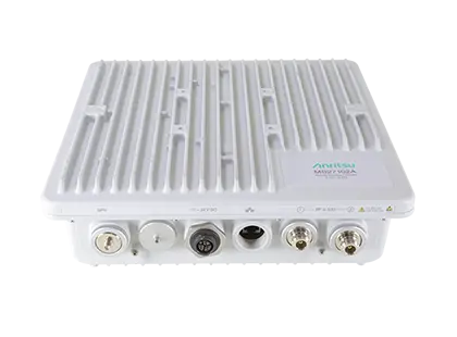
IP67 outdoor remote spectrum monitor covering 9 kHz to 6 GHz with sweep rates up to 24 GHz/s and 20 MHz instantaneous FFT bandwidth.
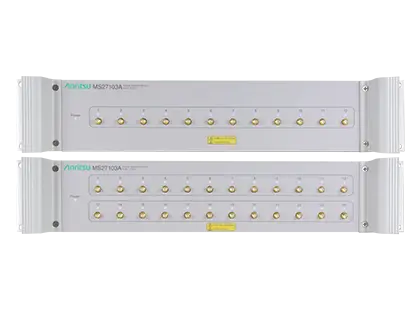
Rack-mountable 9 kHz to 6 GHz remote spectrum monitor with 12 RF inputs (24 optional) and sweep speeds up to 24 GHz/s.
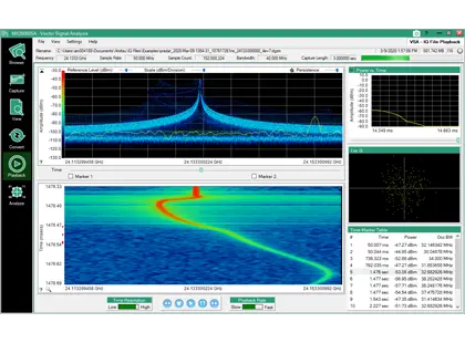
PC software for capturing, playing back, converting and analyzing IQ data from Anritsu spectrum analyzers, with modulation quality measurements.
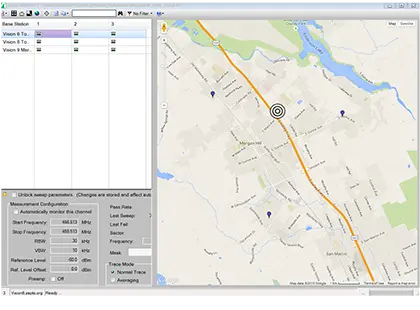
Windows PC software for monitoring, identifying and geo-locating interference signals with networks of Anritsu remote spectrum monitors.