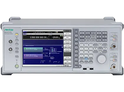
Anritsu MG3710E Vector Signal Generator, 100 kHz to 2.7/4/6 GHz with Dual RF and Dual Waveform Memory Options
Vector signal generator covering 100 kHz to 2.7/4/6 GHz, with up to 160 MHz built-in baseband generation and optional dual RF outputs.
- Frequency range
- 100 kHz to 2.7/4/6 GHz
- Setting range (1st SG)
- 9 kHz to 2.7 GHz
- Setting range (1st SG)
- 9 kHz to 4 GHz
- Setting range (1st SG)
- 9 kHz to 6 GHz
Overview
The Anritsu MG3710E is a multi-function vector signal generator with wideband vector modulation and a built-in baseband waveform generator backed by large-capacity waveform memory. The 1st RF output covers 100 kHz to 2.7, 4 or 6 GHz depending on the frequency option selected, and an optional 2nd RF output is available in the same frequency ranges. It supports the main mobile communications and wireless LAN standards, as well as emerging and proprietary wireless technologies.
Dual RF and dual waveform memory
With the Dual RF and Dual Waveform Memory options, one MG3710E can output up to four independently modulated signals. The baseband signal combination options (MG3710E-048/078) add a second waveform memory to each RF output, so two waveform patterns can be combined with their own frequency offset, level offset and delay. This allows test setups that would otherwise need several synchronized signal generators, such as wanted plus interference signals for receiver blocking tests, wanted plus two CW tones for intermodulation tests, wanted plus delayed signals for multipath tests, and multiple wanted signals for MIMO and LTE-Advanced carrier aggregation testing.
Waveform sources
The instrument can use four types of waveform pattern: built-in standard waveform patterns, optional waveform patterns sold separately (MX3700xxA, MX3700xxB, MX3710xxA), waveforms created with the IQproducer waveform generation software (MX3701xxA), and IQ data from general-purpose signal generation software, such as MATLAB, converted to MG3710E waveform patterns. Standard waveform memory is 64 Msamples and can be expanded to 256 or 1024 Msamples.
Expansion and connectivity
Options include an AWGN generator, a BER measurement function, additional analog modulation inputs, analog IQ input/output, and a universal input/output option that shares local, baseband clock and trigger signals between up to four MG3710E units for phase-coherent MIMO configurations up to 8x8. Up to two USB power sensors can be connected. Remote control is provided over 1000BASE-T Ethernet, GPIB and USB, using SCPI commands or modes compatible with the MG3700A, MS269xA and MS2830A. The command set is shared with the MG3710A.
Key Features
- Frequency coverage of 100 kHz to 2.7/4/6 GHz
- ACLR of -68 dBc (W-CDMA, Test-Model 1, 64DPCH, ≤+5 dBm)
- Output level of +23 dBm (CW, 400 MHz to 3 GHz) with high power extension
- Switching time <600 µs in List/Sweep mode
- Built-in wideband 160 MHz/120 MHz baseband signal generator
- Optional Dual RF with two independent RF outputs
- Optional Dual Waveform Memory with two independently modulated signals per RF output
- Up to four independently modulated signals from one unit
- 64 Msamples standard waveform memory, expandable to 256 or 1024 Msamples
- Pre-installed standard waveform patterns for LTE, W-CDMA/HSDPA, GSM/EDGE, CDMA2000, Bluetooth, GPS, WLAN and broadcast
- 5G NR sub-6 GHz TDD/FDD and LTE-Advanced TDD/FDD signal generation with optional IQproducer software
- Standard analog modulation (AM/FM/ΦM) and pulse modulation
- Optional AWGN generator with C/N ≤40 dB
- Optional BER measurement function, 100 bps to 40 Mbps input bit rate
- Phase-coherent synchronization of up to four units for 8x8 MIMO
- Choice of standard, high stability or rubidium reference oscillator
- Support for up to two USB power sensors
- 1000BASE-T, GPIB and USB remote interfaces with SCPI and MG3700A/MS269xA/MS2830A compatibility modes
Specifications
| Frequency range |
100 kHz to 2.7/4/6 GHz
1st RF with Opt-032/034/036; 2nd RF with Opt-062/064/066. Datasheet setting range starts at 9 kHz
|
|---|---|
|
Setting range (1st SG)
MG3710E-032
|
9 kHz to 2.7 GHz |
|
Setting range (1st SG)
MG3710E-034
|
9 kHz to 4 GHz |
|
Setting range (1st SG)
MG3710E-036
|
9 kHz to 6 GHz |
|
Setting range (2nd SG)
MG3710E-062
|
9 kHz to 2.7 GHz |
|
Setting range (2nd SG)
MG3710E-064
|
9 kHz to 4 GHz |
|
Setting range (2nd SG)
MG3710E-066
|
9 kHz to 6 GHz |
| Resolution | 0.01 Hz |
| Phase offset range |
–180.00 deg. to +180.00 deg.
Resolution: 0.01 deg.
|
| Switching speed |
≤600 μs
Frequency >187.5 MHz, Phase Noise Optimization offset <200 kHz, time from trigger input to final frequency ±0.1 ppm or within 100 Hz when executing List function
|
| Aging rate (standard) |
±1 × 10^-6/year
Without MG3710E-001/002
|
|---|---|
| Temperature characteristics (standard) |
±2.5 × 10^-6 (5 °C to 45 °C)
Without MG3710E-001/002
|
|
Aging rate
MG3710E-001
|
±1 × 10^-10/month
Rubidium reference oscillator
|
|
Temperature characteristics
MG3710E-001
|
±2 × 10^-9 (5 °C to 45 °C)
Rubidium reference oscillator
|
|
Start-up characteristics
MG3710E-001
|
±1 × 10^-9 (7.5 minutes after power-on)
23 °C, referenced to frequency at 24 hours after power-on
|
|
Aging rate
MG3710E-002
|
±1 × 10^-7/year
High stability reference oscillator
|
|
Temperature characteristics
MG3710E-002
|
±2 × 10^-8 (5 °C to 45 °C)
High stability reference oscillator
|
|
Start-up characteristics
MG3710E-002
|
±5 × 10^-7 (2 minutes after power-on), ±5 × 10^-8 (5 minutes after power-on)
23 °C, referenced to frequency at 24 hours after power-on
|
| Setting range |
–110 to +17 dBm
Without high/low power extension
|
|---|---|
|
Setting range
MG3710E-041, MG3710E-071
|
–110 to +30 dBm
With high power extension, without low power extension, without reverse power protection
|
|
Setting range
MG3710E-041, MG3710E-071
|
–110 to +25 dBm
With high power extension and reverse power protection (MG3710E-043/073)
|
|
Setting range
MG3710E-042, MG3710E-072
|
–144 to +17 dBm
With low power extension, without high power extension
|
|
Setting range
MG3710E-041/042, MG3710E-071/072
|
–144 to +30 dBm
With high and low power extension, without reverse power protection; –144 to +25 dBm with MG3710E-043/073
|
|
High power output
MG3710E-041, MG3710E-071
|
+23 dBm (CW, 400 MHz to 3 GHz) |
| Unit | dBm, dBμV (Terminated, Open) |
| Resolution | 0.01 dB |
| Switching speed |
≤600 μs
Frequency >187.5 MHz, within output level accuracy range; time from List trigger until within ±0.2 dB of final output level
|
| Absolute level accuracy |
±0.5 dB
Brochure headline figure
|
| Linearity |
±0.2 dB (typ.)
Brochure headline figure
|
| ATT Hold setting range |
–10 to +10 dB
Limits restricted by the signal output range; resolution 0.01 dB
|
| Connector | N-J Connector, 50 Ω (Front panel) |
|---|---|
| VSWR (4 GHz < f ≤ 6 GHz) |
≤1.9
Output level ≤–7 dBm (≤–10 dBm with MG3710E-043/073)
|
| Maximum reverse input (DC) | ±50 VDC (max.) |
| Maximum reverse input power |
2 W (nom.)
Without reverse power protection
|
|
Maximum reverse input power
MG3710E-043, MG3710E-073
|
20 W (1 MHz < Frequency of Reverse Input Power ≤ 2 GHz) (nom.), 10 W (2 GHz < Frequency of Reverse Input Power ≤ 6 GHz) (nom.) |
| Harmonic spurious |
<–30 dBc (Output Level: ≤+4 dBm, 10 MHz ≤ f ≤ 3 GHz)
CW, Optimize S/N Off, without MG3710E-041 and MG3710E-043/073
|
|---|---|
|
Harmonic spurious
MG3710E-041
|
<–30 dBc (Output Level: ≤+12 dBm, 50 MHz ≤ f ≤ 3 GHz)
CW, Optimize S/N Off, without MG3710E-043/073
|
| Non-harmonic spurious (100 kHz ≤ f ≤ 187.5 MHz) |
<–62 dBc, –70 dBc (typ.)
CW, –30 dBm ≤ output level ≤ +5 dBm, offset ≥10 kHz
|
| Non-harmonic spurious (187.5 MHz < f ≤ 750 MHz) |
<–68 dBc, –76 dBc (typ.)
CW, –30 dBm ≤ output level ≤ +5 dBm, offset ≥10 kHz
|
| Non-harmonic spurious (750 MHz < f ≤ 1.5 GHz) |
<–62 dBc, –76 dBc (typ.)
CW, –30 dBm ≤ output level ≤ +5 dBm, offset ≥10 kHz
|
| Non-harmonic spurious (1.5 GHz < f ≤ 3 GHz) |
<–56 dBc, –70 dBc (typ.)
CW, –30 dBm ≤ output level ≤ +5 dBm, offset ≥10 kHz
|
| Non-harmonic spurious (3 GHz < f ≤ 6 GHz) |
<–50 dBc, –64 dBc (typ.)
CW, –30 dBm ≤ output level ≤ +5 dBm, offset ≥10 kHz
|
| SSB phase noise (100 MHz) |
<–140 dBc/Hz (nom.)
CW, Phase Noise Optimization <200 kHz, 20 kHz offset
|
| SSB phase noise (1 GHz) |
<–131 dBc/Hz (typ.)
CW, Phase Noise Optimization <200 kHz, 20 kHz offset
|
| SSB phase noise (2 GHz) |
<–125 dBc/Hz (typ.)
CW, Phase Noise Optimization <200 kHz, 20 kHz offset
|
| AM depth range |
0 to 100 %
Internal modulation; resolution 0.1 %
|
|---|---|
| AM depth error |
<2 % of setting + 1 % (nom.)
98 MHz ≤ f ≤ 2.7 GHz, modulation rate 1 kHz, sine, depth ≤90 %
|
| FM deviation accuracy |
<2 % of setting + 20 Hz (nom.)
Modulation rate 1 kHz, sine, 20 Hz ≤ FM deviation ≤ 40 kHz
|
| FM deviation resolution | 0.1 Hz |
| PM deviation range |
0 rad. to 160 rad., or [40 MHz ÷ Modulation Rate] (smaller value)
Resolution 0.001 rad.
|
| Pulse modulation on/off ratio | >70 dB (50 MHz ≤ f ≤ 3 GHz), >60 dB (3 GHz < f ≤ 6 GHz) |
| Minimum pulse width | 1 μs (nom.) |
| Pulse rise/fall time |
≤50 ns (nom.)
10 to 90 %
|
| Pulse repetition frequency | DC to 1 MHz (Duty: 50 %) |
| Internal modulation waveforms | Sine wave, Triangular wave, Square wave, Ramp wave (Positive or Negative) |
|
Additional analog modulation input type
MG3710E-050, MG3710E-080
|
AM, FM, ΦM
Input impedance 50 Ω/600 Ω/Hi-Z (100 kΩ/70 pF) (nom.)
|
| Modulation frequency response (850 MHz to 2.2 GHz) |
±0.6 dB (At Center Frequency ±10 MHz), ±1.3 dB (At Center Frequency ±50 MHz)
Without MG3710E-043, channel correction on, –7 dBm, 160 MHz random signal, 18 °C to 28 °C
|
|---|---|
| Modulation frequency response (3.5 GHz/5.8 GHz) |
±0.6 dB (At Center Frequency ±10 MHz), ±1.9 dB (At Center Frequency ±50 MHz)
Without MG3710E-043, channel correction on, –7 dBm, 160 MHz random signal, 18 °C to 28 °C
|
| Vector accuracy, W-CDMA (Test Model 4) |
≤0.62 % (rms)
800 MHz to 900 MHz, 1.8 GHz to 2.2 GHz; ≤0.6 % (rms) typ.; 18 °C to 28 °C, after CAL
|
| Vector accuracy, GSM |
≤0.84 ° (rms)
800 MHz to 900 MHz, 1.8 GHz to 1.9 GHz; ≤0.8 ° (rms) typ.
|
| Vector accuracy, EDGE |
≤0.84 % (rms)
800 MHz to 900 MHz, 1.8 GHz to 1.9 GHz; ≤0.8 % (rms) typ.
|
| Vector accuracy, LTE (20 MHz Test Model 3.1) |
≤0.82 % (rms)
600 MHz to 2.7 GHz and 3.4 GHz to 3.8 GHz; ≤0.8 % (rms) typ.
|
| Carrier leak |
≤–55 dBc (100 MHz ≤ f < 4 GHz), ≤–45 dBc (f ≥ 4 GHz)
18 °C to 28 °C, RMS value 0 dB, after CAL
|
| Image rejection |
≤–50 dBc (200 MHz ≤ f < 4 GHz), ≤–43 dBc (f ≥ 4 GHz)
18 °C to 28 °C, complex CW at 10 MHz or less, after CAL
|
| ACLR (W-CDMA) | -68 dBc (W-CDMA, Test-Model 1, 64DPCH, ≤+5 dBm) |
| ACLR, 300 MHz ≤ f < 800 MHz |
≤–68 dBc/3.84 MHz (5 MHz offset), ≤–70 dBc/3.84 MHz (10 MHz offset)
W-CDMA TestModel1 64 DPCH, 18 °C to 28 °C; output level ≤–2 dBm (≤+5 dBm with MG3710E-041)
|
| ACLR, 800 MHz ≤ f < 1 GHz |
≤–70 dBc/3.84 MHz (5 MHz offset), ≤–71 dBc/3.84 MHz (10 MHz offset)
W-CDMA TestModel1 64 DPCH, 18 °C to 28 °C
|
| ACLR, 1 GHz ≤ f < 1.8 GHz |
≤–69 dBc/3.84 MHz (5 MHz offset), ≤–71 dBc/3.84 MHz (10 MHz offset)
W-CDMA TestModel1 64 DPCH, 18 °C to 28 °C
|
| ACLR, 1.8 GHz ≤ f < 2.2 GHz |
≤–68 dBc/3.84 MHz (5 MHz offset), ≤–71 dBc/3.84 MHz (10 MHz offset)
W-CDMA TestModel1 64 DPCH, 18 °C to 28 °C
|
| ACLR, 2.2 GHz ≤ f ≤ 3 GHz |
≤–65 dBc/3.84 MHz (5 MHz offset), ≤–71 dBc/3.84 MHz (10 MHz offset)
W-CDMA TestModel1 64 DPCH, 18 °C to 28 °C
|
| ACLR, 3 GHz < f ≤ 3.8 GHz |
≤–63 dBc/3.84 MHz (5 MHz offset), ≤–67 dBc/3.84 MHz (10 MHz offset)
Output level ≤–2 dBm (≤–5 dBm with MG3710E-043/073)
|
| Level error compared to CW (98 MHz ≤ f ≤ 6 GHz) |
±0.2 dB
AWGN signal, 5 MHz bandwidth, output level <+1 dBm, 18 °C to 28 °C
|
|
IQ input modulation bandwidth
MG3710E-018
|
Baseband: 80 MHz (nom.), RF: 160 MHz (nom.) |
|---|---|
|
IQ input connector
MG3710E-018
|
BNC-J (Front panel)
Maximum input level –1 V (peak) ≤ I, Q ≤ +1 V (peak); impedance 50 Ω (nom.)
|
|
IQ output voltage range
MG3710E-018
|
–2.5 V to +5 V
Output open, output voltage amplitude + DC offset; BNC-J rear panel
|
| Waveform resolution | 14, 15, 16 bits for each I/Q |
|---|---|
| Modulation bandwidth |
160 MHz/120 MHz
160 MHz with firmware 2.00.00 or later and only with WLAN IQproducer MX370111A and MX370111A-002
|
| Reconstruction filter | 80 MHz |
| Internal baseband reference clock |
20 kHz to 200 MHz/160 MHz
Resolution 0.001 Hz
|
| Waveform memory (standard) |
64 Msamples
Per RF output
|
|
Waveform memory
MG3710E-045, MG3710E-075
|
256 Msamples |
|
Waveform memory
MG3710E-046, MG3710E-076
|
1024 Msamples |
| Maximum patterns |
4096 /waveform memory
Max. package count 4096; minimum 128 samples per pattern
|
|
C/N ratio absolute value
MG3710E-049, MG3710E-079
|
≤40 dB |
|---|---|
|
Bandwidth limit filter
MG3710E-049, MG3710E-079
|
From 20 % to 80 % of waveform sampling rate |
| Sweep function | Sets frequency and level sweep at 1000-point resolution |
|---|---|
| List function | Sets sweep points for both frequency and level individually to 500 points |
|
Input bit rate
MG3710E-021
|
100 bps to 40 Mbps |
|---|---|
|
Input signal
MG3710E-021
|
Data, Clock, Enable
AUX connector (rear panel), TTL
|
|
Measurable pattern
MG3710E-021
|
PN9, PN11, PN15, PN20, PN23, ALL0, ALL1, 01, PN9 fix, PN11 fix, PN15 fix, PN20 fix, PN23 fix, User Define |
|
Measurement mode
MG3710E-021
|
Single, Endless, Continuous |
| External reference input |
5, 10, 13 MHz
BNC-J rear panel, 50 Ω (nom.); –15 dBm ≤ level ≤ +20 dBm (AC coupled)
|
|---|---|
| Reference signal output |
10 MHz
BNC-J rear panel, output level ≥0 dBm (AC coupled)
|
|
Local oscillator input/output
MG3710E-017
|
98 MHz to 6 GHz
SMA-J rear panel, 50 Ω (nom.)
|
| Ethernet | 10/100/1000 Base-T, RJ-45 (Rear panel) |
| GPIB | IEEE488 Bus connector (IEEE488.2, Rear panel) |
| USB | USB-B (USB2.0, Rear panel); USB-A (USB2.0, Front panel: 2 ports, Rear panel: 2 ports) |
| Monitor output | Mini D-Sub connector (compatible with VGA, Rear panel) |
| Remote command |
Built-in SCPI, MG3700A/MS269xA/MS2830A compatibility modes
Common with MG3710A
|
| Display | XGA-color LCD (Diagonal: 213 mm, Resolution: 1024 × 768) |
|---|
| Dimensions |
426 (W) × 177 (H) × 390 (D) mm
Excluding projections
|
|---|---|
| Mass |
≤13.7 kg
With MG3710E-032, 034 or 036, excluding other options; ≤17 kg including all options
|
| Power voltage |
100 V(ac) to 120 V(ac), 200 V(ac) to 240 V(ac)
50 Hz/60 Hz
|
| Power consumption |
≤350 VA
Including all options
|
| Operating temperature | +5 °C to +45 °C |
| Storage temperature | –20 °C to +60 °C |
Specifications are taken from the manufacturer's documentation. See the datasheet for complete and current values.
Applications
- Receiver blocking testing with wanted and interference signals
- Receiver intermodulation testing
- Multipath testing with delayed signals
- MIMO testing
- LTE-Advanced carrier aggregation testing
- 5G NR sub-6 GHz device testing
- Multi-standard radio (MSR) evaluation
- Wireless LAN IEEE 802.11ac signal generation
- 5 GHz band WLAN DFS testing
- Land mobile radio testing
- O-RAN equipment testing
- R&D simulation with custom waveforms
Options & Accessories
| Option | Description |
|---|---|
| MG3710E-032 | 1stRF 100 kHz to 2.7 GHz — 1st RF frequency range; one 1st RF option required |
| MG3710E-034 | 1stRF 100 kHz to 4 GHz — 1st RF frequency range; one 1st RF option required |
| MG3710E-036 | 1stRF 100 kHz to 6 GHz — 1st RF frequency range; one 1st RF option required |
| MG3710E-062/162 | 2ndRF 100 kHz to 2.7 GHz — 1xx: Retrofit |
| MG3710E-064/164 | 2ndRF 100 kHz to 4 GHz — 1xx: Retrofit |
| MG3710E-066/166 | 2ndRF 100 kHz to 6 GHz — 1xx: Retrofit |
| MG3710E-001/101 | Rubidium Reference Oscillator — 1xx: Retrofit |
| MG3710E-002/102 | High Stability Reference Oscillator — 1xx: Retrofit |
| MG3710E-011/111 | Secondary HDD — 1xx: Retrofit |
| MG3710E-014/114 | Removable HDD, Windows 10 — 1xx: Retrofit |
| MG3710E-017/117 | Universal Input/Output — 1xx: Retrofit |
| MG3710E-021/121 | BER Test Function — 1xx: Retrofit |
| MG3710E-018/118 | Analog IQ Input/Output — 1xx: Retrofit |
| MG3710E-041/141 | High Power Extension for 1stRF — 1xx: Retrofit |
| MG3710E-042/142 | Low Power Extension for 1stRF — 1xx: Retrofit |
| MG3710E-043/143 | Reverse Power Protection for 1stRF — 1xx: Retrofit |
| MG3710E-045/145 | ARB Memory Upgrade 256 Msample for 1stRF — 1xx: Retrofit |
| MG3710E-046/146 | ARB Memory Upgrade 1024 Msample for 1stRF — 1xx: Retrofit |
| MG3710E-048/148 | Combination of Baseband Signal for 1stRF — 1xx: Retrofit |
| MG3710E-049/149 | AWGN for 1stRF — 1xx: Retrofit |
| MG3710E-050/150 | Additional Analog Modulation Input for 1st RF — 1xx: Retrofit |
| MG3710E-071/171 | High Power Extension for 2ndRF — 1xx: Retrofit |
| MG3710E-072/172 | Low Power Extension for 2ndRF — 1xx: Retrofit |
| MG3710E-073/173 | Reverse Power Protection for 2ndRF — 1xx: Retrofit |
| MG3710E-075/175 | ARB Memory Upgrade 256 Msample for 2ndRF — 1xx: Retrofit |
| MG3710E-076/176 | ARB Memory Upgrade 1024 Msample for 2ndRF — 1xx: Retrofit |
| MG3710E-078/178 | Combination of Baseband Signal for 2ndRF — 1xx: Retrofit |
| MG3710E-079/179 | AWGN for 2ndRF — 1xx: Retrofit |
| MG3710E-080/180 | Additional Analog Modulation Input for 2nd RF — 1xx: Retrofit |
| MX370073B | DFS Radar Pattern [For FCC/Japan MIC] |
| MX370075A | DFS (ETSI) Waveform Pattern [For ETSI] |
| MX370084A | ISDB-Tmm Waveform Pattern |
| MX371054A | Interference Waveform Pattern for LTE Receiver Test |
| MX371055A | Interference Waveform Pattern for 5G NR Receiver Test |
| MX370101A | HSDPA/HSUPA IQproducer |
| MX370102A | TDMA IQproducer |
| MX370103A | CDMA2000 1xEV-DO IQproducer |
| MX370104A | Multi-carrier IQproducer |
| MX370106A | DVB-T/H IQproducer |
| MX370107A | Fading IQproducer |
| MX370108A | LTE IQproducer |
| MX370108A-001 | LTE-Advanced FDD Option — Requires MX370108A |
| MX370110A | LTE TDD IQproducer |
| MX370110A-001 | LTE-Advanced TDD Option — Requires MX370110A |
| MX370111A | WLAN IQproducer |
| MX370111A-002 | 802.11ac (160 MHz) Option — Requires MX370111A |
| MX370112A | TD-SCDMA IQproducer |
| MX370113A | 5GNR TDD sub-6GHz IQproducer |
| MX370114A | 5GNR FDD sub-6GHz IQproducer |
| MG3710E-ES210 | 2 Years Extended Warranty Service |
| MG3710E-ES310 | 3 Years Extended Warranty Service |
| MG3710E-ES510 | 5 Years Extended Warranty Service |
Documents & Resources
Related Products
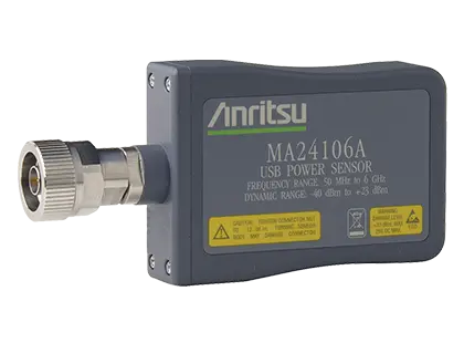
True-RMS USB power sensor that measures average power from 50 MHz to 6 GHz over a 63 dB dynamic range without a separate power meter.
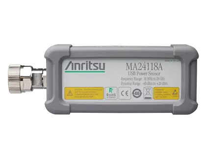
True-RMS USB power sensor measuring average power from 10 MHz to 18 GHz over a 60 dB dynamic range.
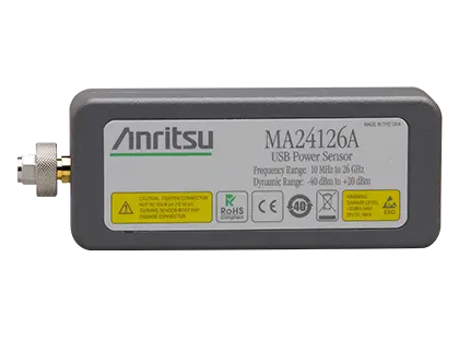
True-RMS USB power sensor measuring average power from 10 MHz to 26 GHz over a 60 dB dynamic range.