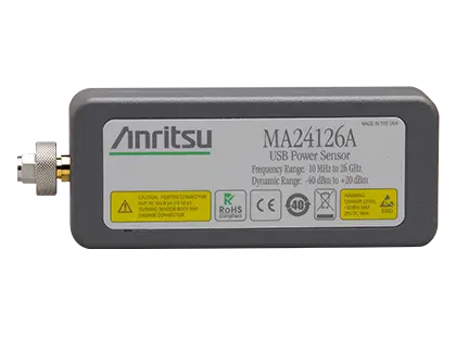
MA24126A Microwave USB Power Sensor, 10 MHz to 26 GHz
True-RMS USB power sensor measuring average power from 10 MHz to 26 GHz over a 60 dB dynamic range.
- Frequency range
- 10 MHz to 26 GHz
- Dynamic range (CW)
- –40 dBm to +20 dBm
- Dynamic range (Timeslot)
- –40 dBm to +20 dBm
- Dynamic range (Scope)
- –40 dBm to +20 dBm
Overview
The Anritsu MA24126A is a microwave USB power sensor that measures average power from 10 MHz to 26 GHz over 60 dB of dynamic range. It uses a dual-path architecture in which two diode detector paths are kept in their square-law region and the appropriate path is selected for the signal level, giving True-RMS results comparable to a thermal sensor for CW, multi-tone and digitally modulated signals. A built-in attenuator at the input improves SWR and reduces mismatch error, and a DC block protects the sensor from RF signals carrying DC content.
The sensor contains a microcontroller, signal conditioning, ADCs and power supply, so it operates as a complete power meter without a benchtop unit. All calibration factors, linearity and temperature corrections are stored inside the sensor, and the USB cable carries only corrected digital power data, which removes the need for a 1 mW reference calibrator. Calibration standards are traceable to NIST and periodic calibration is available through Anritsu service centers.
Triggering and measurement modes
The MA24126A supports a software-based internal trigger and an external trigger input on an MCX connector. In Scope mode the sensor displays power versus time with gate and fence settings to include or exclude portions of the waveform. In Time Slot mode it reports the average power of each slot in TDMA signals such as GSM/EDGE, with up to 128 slots, a 300 ms capture time and user-definable exclusion periods. The ADC samples at 140,000 samples per second, and positive or negative trigger delay can be applied.
Compatibility
The sensor connects to a PC running Microsoft Windows and is controlled with the PowerXpert application, which provides data logging, power-versus-time graphs and a large numerical display. It also works with Option-19-enabled Anritsu handheld and benchtop instruments, including Site Master, Spectrum Master, Cell Master, BTS Master, VNA Master and the MS271xB Economy Microwave Spectrum Analyzers, via a USB A/micro-B cable. Scope and Time Slot measurements require a PC. Multiple sensors can be controlled from a single PC, and a USB-to-LAN converter allows remote monitoring beyond the 5 m USB cable limit.
Key Features
- Broad frequency range (10 MHz to 26 GHz)
- True RMS measurements over 60 dB dynamic range
- NIST traceable calibrations
- Compatible with Anritsu handhelds
- Built-in internal and external trigger (only used with PC)
- High power handling (+33 dBm)
- 1 mW calibration need eliminated
- Silicone protective covering for additional field durability
- Worldwide calibration and service centers
- Dual-path architecture keeps diode detectors in the square-law region
- Built-in attenuator minimises mismatch error
- DC block at the sensor input
- Scope mode with gate and fence feature
- Time Slot mode with up to 128 slots and 300 ms capture time
- Two-colour LED reports sensor status
- K connector designed for use with a torque wrench
- Software toolkit with sample source code for ATE control
- Auto averaging and auto ranging
Specifications
| Frequency range | 10 MHz to 26 GHz |
|---|---|
| Dynamic range (CW) | –40 dBm to +20 dBm |
| Dynamic range (Timeslot) | –40 dBm to +20 dBm |
| Dynamic range (Scope) | –40 dBm to +20 dBm |
| SWR |
< 1.90, 10 MHz to 50 MHz; < 1.17, 50 MHz to 150 MHz; < 1.12, 150 MHz to 2 GHz; < 1.22, 2 GHz to 12 GHz; < 1.25, 12 GHz to 18 GHz; < 1.35, 18 GHz to 26 GHz
Web page states < 1.17 for 10 MHz to 150 MHz without the 10 MHz to 50 MHz band; datasheet value used
|
| Signal channel rise time | 8 µs typical |
| Video bandwidth | 50 kHz typical |
| Sampling rate | 140 ks/s, typical |
| Measurement ranges |
Range 1, +20 dBm to –7 dBm typical; Range 2, –7 dBm to –40 dBm typical
Auto ranging between range 1 and 2
|
| Linearity |
< 3%
Measurement linearity error referenced to an ideal thermal power sensor measurement of CW signals operating at 26 GHz
|
|---|---|
| Cal factor |
< 3.5% at 10 MHz; < 2.0%, 50 MHz to 2 GHz; < 2.5%, 3 GHz to 8 GHz; < 3.0%, 9 GHz to 15 GHz; < 3.5%, 16 GHz to 26 GHz
Expanded uncertainty with K=2 for absolute power measurements on CW signal at 0 dBm at calibration frequencies 10 MHz, 50 MHz, 100 MHz, 300 MHz, 500 MHz, and 1 GHz to 26 GHz in 1 GHz increments
|
| Noise |
< 8 µW, Range 1; < 40 nW, Range 2
Expanded uncertainty with K=2 after zero operation, 1 average, 20 ms aperture time for 5 minutes; noise falls as the square root of the number of averages and aperture time
|
| Zero set |
< 1 µW, Range 1; < 10 nW, Range 2
Expanded uncertainty with K=2 after zero operation, 1 average, 20 ms aperture time for 5 minutes
|
| Zero drift |
< 0.5 µW, Range 1; < 3 nW, Range 2
Expanded uncertainty with K=2 after one hour warm-up and zero operation, 1 average, 20 ms aperture time, temperature within ±1 ºC
|
| Effect of temperature | < 1.4% |
| Effect of digital modulation |
< 0.5%, < +18 dBm; < 1.4%, > +18 dBm
Measurement error with reference to a CW signal of equal power and frequency at 25 ºC
|
| Measurand | Average power |
|---|---|
| Measurement resolution |
0.01 dB max via PowerXpert, 0.001 dB max via remote command
Resolution in PowerXpert is 2 digits after the decimal; native sensor resolution is 3 digits after the decimal
|
| Offset correction |
–100 dB to +150 dB
Available only through the PowerXpert application; no remote command in the sensor firmware
|
| Averaging | Auto, Manual |
| Averaging type | Moving, Repeat |
| Number of averages (manual) |
1 to 40,000
Maximum in Continuous Average and Timeslot modes is 40,000; in Scope mode the maximum equals 8231936 divided by data points
|
| Auto average resolution |
1 dB, 0.1 dB, 0.01 dB, 0.001 dB
0.001 dB averaging resolution is not available with the PowerXpert application
|
| Auto average source (slot # or scope data point number) | Timeslot: 1 to 128; Scope: 1 to 1024 |
| Duty cycle correction | 0.01% to 100% |
|---|---|
| Aperture time | 0.01 ms to 300 ms |
| Measurement time |
N x (Capture Time x 2.5) + Td + Tcom
Data throughput at the A end of the USB A to Micro-B cable; Td = 0 for Capture Time > 9 ms, 3 ms for 2 ms < Capture Time < 9 ms, 5 ms for Capture Time < 2 ms; Tcom = 5 ms command processing time
|
| Capture time | 0.01 to 300 ms |
|---|---|
| Data points | 1 to 1024 |
| Resolution | 0.007 ms, max via remote command; 0.01 ms, max via PowerXpert |
| Measurement time |
N x (Capture Time x 3.75) + (Pn x Tdp) + Tcom
N = number of repeat averages (1 for moving average); Pn = number of points; Tdp = 0.05 ms communication delay per point; Tcom = 5 ms command processing time
|
| Maximum number of slots | 128 |
|---|---|
| Slot width | 0.01 ms to 100 ms |
| Maximum capture time | 300 ms (slot width x number of slots) |
| Resolution | 0.007 ms, max via remote command; 0.01 ms, max via PowerXpert |
| Exclusion periods | Start exclusion 0 ms to 10 ms; End exclusion 0 ms to 10 ms |
| Measurement time |
N x (Capture Time x 3.75) + (Pn x Tdp) + Tcom
N = number of repeat averages (1 for moving average); Pn = number of points; Tdp = 0.05 ms communication delay per point; Tcom = 5 ms command processing time
|
| Source |
Bus, Continuous, Internal and External
Bus trigger not available in the PowerXpert application
|
|---|---|
| Internal trigger dynamic range | –20 dBm to +20 dBm |
| Internal trigger level accuracy | ± 0.5 dB, typical |
| Internal trigger slope | Positive or negative |
| Internal trigger delay range | –5 ms to +10 s |
| Internal trigger delay resolution | 10 µs |
| External trigger impedance | 100 kΩ |
| External trigger type | TTL/CMOS |
| External trigger slope | Positive or negative |
| External trigger delay range | –5 ms to +10 s |
| External trigger delay resolution | 10 µs |
| External trigger positive threshold voltage | 2.0 V typical |
| External trigger negative threshold voltage | 1.2 V typical |
| External trigger hysteresis | 0.8 V typical |
| RF connector |
K male
Web page lists K (m)
|
|---|---|
| Interface to host | USB 2.0 full speed (compatible with USB 1.0 and 1.1) |
| Current consumption | 150 mA, typical |
| External trigger input | MCX (female), 12 V max |
| Damage levels at RF port | +33 dBm, ± 20 V DC |
| Size |
25 mm x 45 mm x 110 mm, excluding N connector and silicone protective covering
Family datasheet value stated for the N-connector models
|
| Weight | 230 g (0.51 lb) |
| Operating temperature range |
0 ºC to 50 ºC
Tests performed per MIL-PRF-28800F (Class 2)
|
|---|---|
| Storage temperature range | –51 ºC to +71 ºC |
| Humidity | 45% relative humidity at 55 ºC (non-condensing); 75% relative humidity at 40 ºC (non-condensing); 95% relative humidity at 30 ºC (non-condensing) |
| Shock | 30 g half-sine, 11 ms duration |
| Vibration | Sinusoidal: 5 Hz to 55 Hz, 3 g max.; Random: 10 Hz to 500 Hz, Power Spectral Density: 0.03 g²/Hz |
| EMC | EN 61326 |
| Safety | EN 61010-1 |
| Processor and RAM | Minimum: Equivalent to Intel Pentium III with 1 GB RAM or Intel Pentium IV with 512 MB RAM; Recommended: Equivalent to Intel Pentium IV with 1 GB RAM |
|---|---|
| Operating system | Microsoft Windows 7, Windows Vista, Windows XP and Windows 2000 |
| Hard-disk free space | 100 MB, minimum |
| Display resolution | 1024 × 768, minimum |
| Interface | USB 2.0 full speed (compatible with USB 1.0 and 1.1) |
Specifications are taken from the manufacturer's documentation. See the datasheet for complete and current values.
Applications
- General purpose RF and microwave power measurement
- Aerospace and defense
- Satellite
- Cellular base station installation and maintenance
- Microwave point-to-point radio installation and maintenance
- Production test and ATE systems
- R&D of wireless devices and systems
- TDMA time slot measurements (GSM, WiMAX, TD-SCDMA)
- Burst power measurements
- Antenna measurements over LAN
- Remote power monitoring
Included
- 10585-00021 Quick Start Guide
- 2000-1605-R 1.5 m BNC (m) to MCX (m) cable
- 2000-1606-R 1.8 m USB A to Micro-B cable with latch
- PowerXpert data analysis and control software
- Software toolkit with sample program and source code
Options & Accessories
| Option | Description |
|---|---|
| MA24126A-097 | Option 97, Accredited Calibration to ISO17025 and ANSI/NCSL Z540 — Test report and uncertainty data included. |
| MA24126A-098 | Option 98, Standard calibration to ISO17025 and ANSI/NCSL Z540 |
| MA24126A-099 | Option 99, Premium calibration to ISO17025 and ANSI/NCSL Z540 — Test report and uncertainty data included. |
| 01-200 | Calibrated torque wrench for N connector |
| 01-204 | Calibrated torque wrench for K and V connectors |
| 2000-1614-R | 5.0 m USB A to Micro-B cable with latch |
| 3-1010-123 | Power attenuator, DC to 8.5 GHz — 30 dB, 50 W, 50 Ω, N (m) to N (f) |
| 3-1010-124 | Power attenuator, DC to 8.5 GHz — 40 dB, 100 W, 50 Ω, N (m) to N (f) |
| 3-1010-122 | Power attenuator, DC to 12.4 GHz — 20 dB, 5 W, 50 Ω, N (m) to N (f) |
| 42N50-20 | Power attenuator, DC to 18 GHz — 20 dB, 5 W, 50 Ω, N (m) to N (f) |
| 42N50-30 | Power attenuator, DC to 18 GHz — 30 dB, 50 W, 50 Ω, N (m) to N (f) |
| 41KB-3 | Power attenuator, DC to 26.5 GHz — 3 dB, 50 Ω, K (m) to K (f) |
| 41KB-6 | Power attenuator, DC to 26.5 GHz — 6 dB, 50 Ω, K (m) to K (f) |
| 41KB-10 | Power attenuator, DC to 26.5 GHz — 10 dB, 50 Ω, K (m) to K (f) |
| 41KB-20 | Power attenuator, DC to 26.5 GHz — 20 dB, 50 Ω, K (m) to K (f) |
| 43KB-3 | Power attenuator, DC to 26.5 GHz — 3 dB, 50 Ω, K (m) to K (f) |
| 43KB-6 | Power attenuator, DC to 26.5 GHz — 6 dB, 50 Ω, K (m) to K (f) |
| 43KB-10 | Power attenuator, DC to 26.5 GHz — 10 dB, 50 Ω, K (m) to K (f) |
| 43KB-20 | Power attenuator, DC to 26.5 GHz — 20 dB, 50 Ω, K (m) to K (f) |
| 510-90 | Precision coaxial adapter, DC to 3.3 GHz — N (m) to 7/16 DIN (f) |
| 510-91 | Precision coaxial adapter, DC to 3.3 GHz — N (f) to 7/16 DIN (f) |
| 510-92 | Precision coaxial adapter, DC to 3.3 GHz — N (m) to 7/16 DIN (m) |
| 510-93 | Precision coaxial adapter, DC to 3.3 GHz — N (f) to 7/16 DIN (m) |
| 33NFNF50B | Precision coaxial adapter, DC to 18 GHz — N (f) to N (f) |
| 33NNF50B | Precision coaxial adapter, DC to 18 GHz — N (m) to N (f) |
| 33NN50B | Precision coaxial adapter, DC to 18 GHz — N (m) to N (m) |
| 34AN50 | Precision coaxial adapter, DC to 18 GHz — GPC-7 to N (m) |
| 34ANF50 | Precision coaxial adapter, DC to 18 GHz — GPC-7 to N (f) |
| 34NFK50 | Precision coaxial adapter, DC to 18 GHz — N (f) to K (m) |
| 34NFKF50 | Precision coaxial adapter, DC to 18 GHz — N (m) to K (f) |
| 34NK50 | Precision coaxial adapter, DC to 18 GHz — N (m) to K (m) |
| 34NKF50 | Precision coaxial adapter, DC to 18 GHz — N (m) to K (f) |
| 1091-26 | Precision coaxial adapter, DC to 18 GHz — N (m) to SMA (m) |
| 1091-27 | Precision coaxial adapter, DC to 18 GHz — N (m) to SMA (f) |
| 1091-80-R | Precision coaxial adapter, DC to 18 GHz — N (f) to SMA (m) |
| 1091-81-R | Precision coaxial adapter, DC to 18 GHz — N (f) to SMA (f) |
Documents & Resources
Related Products
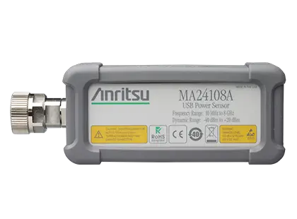
True-RMS USB power sensor measuring average power from 10 MHz to 8 GHz over 60 dB of dynamic range, with internal and external triggering.
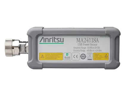
True-RMS USB power sensor measuring average power from 10 MHz to 18 GHz over a 60 dB dynamic range.