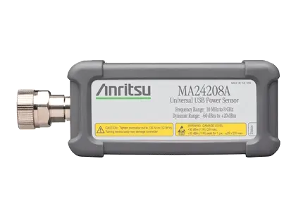
MA24208A Microwave Universal USB Power Sensor, 10 MHz to 8 GHz True-RMS
True-RMS USB power sensor measuring average power from 10 MHz to 8 GHz over an 80 dB dynamic range with no benchtop meter required.
- Frequency Range
- 10 MHz to 8 GHz
Overview
The Anritsu MA24208A is a USB power sensor for average power measurements from 10 MHz to 8 GHz over 80 dB of dynamic range. It uses a patented triple-path architecture that delivers True-RMS readings across the full frequency and power range, comparable to thermal sensors, so CW, multi-tone and digitally modulated signals can be measured without dependence on modulation bandwidth.
Digital signal processing in the sensor supports more than 1,600 continuous readings per second and more than 11,000 buffered readings per second. A low-noise design removes the need to zero the sensor before measuring signals above -45 dBm, and no 1 mW reference calibration is required.
Triggering
Internal and external trigger sources with auto, single, multiple and standby arming allow individual slot power measurements on TDMA waveforms and burst power measurements on periodic and non-periodic signals. External trigger latching supports pulses as narrow as 20 ns.
Control and connectivity
The sensor connects to a PC over USB 2.0 and is controlled either through remote programming commands or through PowerXpert, Anritsu's free application software. It is also compatible with most Anritsu RF and microwave handheld instruments; the high accuracy power meter software option (for example Option 19) may be required on the instrument.
Damage protection of +30 dBm CW and +34 dBm for pulses under 10 µs, together with a removable silicone protective covering, give the sensor additional durability for field use. Calibration is NIST traceable.
Key Features
- Frequency range: 10 MHz to 8 GHz
- Power measurement range: +20 dBm to -60 dBm (80 dB dynamic range)
- True RMS measurements, independent of modulation
- Fast measurement speed: >1,600 readings/s continuous, >11,000 readings/s buffered
- High damage level: +30 dBm CW, +34 dBm peak < 10 µs
- No zeroing required for signals above -45 dBm
- No 1 mW reference calibration required
- Internal and external triggering with auto, single, multiple and standby arming
- External trigger latching for pulses as narrow as 20 ns
- NIST traceable calibration
- Compatible with select Anritsu handheld instruments and PCs; no benchtop power meter needed
- Free PowerXpert PC application software
- Removable silicone protective covering for field durability
- Worldwide calibration and service centers
Specifications
| Frequency Range | 10 MHz to 8 GHz |
|---|
| Dynamic Range | –60 dBm to +20 dBm |
|---|---|
| Measurement Range 1 |
+20 dBm to +4 dBm
approximate
|
| Measurement Range 2 |
<+4 dBm to –16 dBm
approximate
|
| Measurement Range 3 |
<–16 dBm to –60 dBm
approximate
|
| Ranging | Auto and fixed ranging available |
| Damage Levels at RF Port | +30 dBm, ±20 V DC (+34 dBm peak < 10 μs pulse and 10 % duty cycle), minimum |
| Measurand | Average power |
| Measurement Resolution | 0.01 dB max via PowerXpert, 0.001 dB max via remote command |
| Offset Correction |
–100 dB to +150 dB
Available only through the PowerXpert application; no remote command in the sensor firmware
|
| VSWR, max (≤150 MHz) | 1.17:1 |
|---|---|
| VSWR, max (>150 MHz to 2 GHz) | 1.12:1 |
| VSWR, max (>2 GHz to 12.4 GHz) |
1.22:1
MA24208A frequency range ends at 8 GHz
|
| –60 to <–16 dBm |
0.14 (≤0.05 GHz), 0.14 (>0.05 to 2 GHz), 0.14 (>2 to 12.4 GHz)
Two sigma confidence level for CW measurement after zero operation; includes calibration factor and linearity over temperature, excludes mismatch, zero set and drift, and noise
|
|---|---|
| –16 to <+4 dBm |
0.14 (≤0.05 GHz), 0.14 (>0.05 to 2 GHz), 0.13 (>2 to 12.4 GHz)
Two sigma confidence level for CW measurement after zero operation
|
| +4 to +20 dBm |
0.14 (≤0.05 GHz), 0.15 (>0.05 to 2 GHz), 0.15 (>2 to 12.4 GHz)
Two sigma confidence level for CW measurement after zero operation
|
| –60 to <–16 dBm |
0.13 (≤0.05 GHz), 0.12 (>0.05 to 2 GHz), 0.14 (>2 to 12.4 GHz)
Two sigma confidence level for CW measurement after zero operation
|
|---|---|
| –16 to <+4 dBm |
0.11 (≤0.05 GHz), 0.10 (>0.05 to 2 GHz), 0.13 (>2 to 12.4 GHz)
Two sigma confidence level for CW measurement after zero operation
|
| +4 to +20 dBm |
0.11 (≤0.05 GHz), 0.10 (>0.05 to 2 GHz), 0.10 (>2 to 12.4 GHz)
Two sigma confidence level for CW measurement after zero operation
|
| Zero Set (–60 to <–16 dBm range) |
3.32E-10 W (–64.78 dBm)
Three sigma; one hour warm-up followed by a Zero operation, 256 averages, 40 ms aperture, temperature within ±1 °C
|
|---|---|
| Zero Set (–16 to <+4 dBm range) |
3.87E-08 W (–44.12 dBm)
Three sigma confidence level
|
| Zero Set (+4 to +20 dBm range) |
1.07E-06 W (–29.70 dBm)
Three sigma confidence level
|
| Zero Drift (–60 to <–16 dBm range) |
3.44E-10 W (–64.64 dBm)
Two sigma value of the reported power over one hour
|
| Zero Drift (–16 to <+4 dBm range) |
4.29E-08 W (–43.67 dBm)
Two sigma value of the reported power over one hour
|
| Zero Drift (+4 to +20 dBm range) |
9.96E-07 W (–30.02 dBm)
Two sigma value of the reported power over one hour
|
| Noise (–60 to <–16 dBm range) |
1.23E-10 W
Two sigma noise at 10.2 seconds of integration time; noise uncertainty expressed with three sigma confidence level
|
| Noise (–16 to <+4 dBm range) |
1.01E-08 W
Two sigma noise at 10.2 seconds of integration time
|
| Noise (+4 to +20 dBm range) |
8.56E-07 W
Two sigma noise at 10.2 seconds of integration time
|
| Effect of Digital Modulation (–60 to <–16 dBm range) |
–0.048 to 0.080 dB
Measurement error vs. a CW signal of equal power and frequency, 20 °C to 30 °C, Normal mode, average power ≤+20 dBm
|
| Effect of Digital Modulation (–16 to <+4 dBm range) |
–0.038 to 0.088 dB
Measurement error vs. a CW signal of equal power and frequency, 20 °C to 30 °C, Normal mode
|
| Effect of Digital Modulation (+4 to +20 dBm range) |
–0.055 to 0.067 dB
Measurement error vs. a CW signal of equal power and frequency, 20 °C to 30 °C, Normal mode
|
| Signal Channel Rise Time |
8 μs
characteristic
|
|---|---|
| Sampling Rate | 140 kS/s |
| Source |
Bus, Continuous, Internal, External
Bus trigger is not available in PowerXpert application
|
|---|---|
| Arm Type (for Internal/External) | Auto, Single, Multiple, Standby |
| Dynamic Range | –35 dBm to +20 dBm |
|---|---|
| Level Accuracy |
±0.5 dB
characteristic
|
| Slope | Positive or Negative |
| Delay Range | –5 ms to +10 s |
| Delay Resolution | 10 μs |
| Hysteresis | 0 to 10 dB, with 0.1 dB resolution |
| Trigger Hold Off | 0 to 10 sec, with 0.01 ms resolution |
| External Trigger Input | MCX (female), 5.5 V maximum |
|---|---|
| Impedance | 4 kΩ nominal |
| Type | TTL/CMOS |
| Slope | Positive or Negative |
| Delay Range | –5 ms to +10 s |
| Delay Resolution | 10 μs |
| High Level Input Voltage | 2.3 V min, 3.0 V max |
| Low Level Input Voltage | 1.3 V min, 1.6 V max |
| Latency |
7.1 μs max
Time delay between the defined edge of the applied trigger and the sensor switching into the triggered state
|
| Trigger Pulse Width | 20 ns min |
| Trigger Repetition Period | 7.1 μs min |
| Trigger Hold Off | 0 s to 10 s with 0.01 ms resolution |
| Averaging | Auto, Manual |
|---|---|
| Type | Moving, Repeat |
| Number of Averages (Manual) |
1 to 65,536
Maximum in Continuous Average and Timeslot modes; in Scope mode the maximum equals 16,777,216 divided by the number of data points
|
| Auto Average Resolution |
1 dB, 0.1 dB, 0.01 dB
0.001 dB averaging resolution is not available with the PowerXpert application
|
| Auto Average Source | Timeslot Number: 1 to 128; Scope Data Point Number: 1 to 16,384 |
| Duty Cycle Correction | 0.01 % to 100 % |
|---|---|
| Aperture Time | 0.01 ms to 1 s |
| Measurement Speed, Continuous |
>1,600 readings/s
Minimum aperture, one average; speed may vary with the CPU controlling the sensor (specified with Intel Core i5-3550 at 3.30 GHz)
|
| Measurement Speed, Buffered |
>11,000 readings/s
Minimum aperture, one average
|
| Buffer Size | 8192 |
| Capture Time | 0.01 ms to 1 s |
|---|---|
| Data Points | 1 to 16,384 |
| Resolution | 0.01 ms max |
| Maximum Number of Slots | 128 |
|---|---|
| Slot Width | 0.01 ms to 100 ms |
| Maximum Capture Time | 1000 ms (slot width x number of slots) |
| Resolution | 0.01 ms max via remote command, 0.01 ms max via PowerXpert |
| Exclusion Periods | Start Exclusion: 0 ms to 10 ms; End Exclusion: 0 ms to 10 ms |
| Number of Measurements | 1 to 1000 |
|---|---|
| Input Parameters | Frequency (GHz), aperture time (ms), averages |
| Processor and RAM |
Minimum: Equivalent to Intel Pentium III with 1 GB RAM or Intel Pentium IV with 512 MB RAM; Recommended: Equivalent to Intel Pentium IV with 1 GB RAM
PowerXpert version 3.0 or greater
|
|---|---|
| Operating System | Microsoft Windows 8, Windows 7, and Windows XP |
| Hard-Disk Free Space | 100 MB minimum |
| Display Resolution | 1024 × 768 minimum |
| Interface | USB 2.0 high speed |
| RF Connector | N male |
|---|---|
| Interface to Host |
USB 2.0 high speed
USB Micro-B port for connectivity to PC or Anritsu handheld instrument
|
| Current Consumption |
410 mA to 450 mA
characteristic (20 ºC to 30 ºC)
|
| Size |
110 mm x 46 mm x 25.6 mm
Excluding N connector and silicone protective covering
|
| Weight | 397 g (0.88 lb) |
| Warranty | 1 year |
| Calibration Cycle |
12 months
Anritsu recommended calibration interval
|
| Warm-Up Time | 60 minutes |
| Operating Temperature Range |
0 ºC to 50 ºC
Tests performed per MIL-PRF-28800F (Class 3)
|
|---|---|
| Storage Temperature Range | –40 ºC to +71 ºC |
| Relative Humidity (non-condensing) | 45 % at 50 ºC, 75 % at 40 ºC, 95 % at 30 ºC |
| Altitude | 4600 m operational max |
| Shock | 30 g half-sine, 11 ms duration |
| Vibration | Sinusoidal: 5 Hz to 55 Hz, 3 g max; Random: 10 Hz to 500 Hz, 2.34 g rms; Power Spectral Density: 0.01 g²/Hz |
| European Union EMC | 2014/30/EU, EN 61326:2013, CISPR 11/EN 55011, IEC/EN 61000-4-2/3/4/5/6/8/11 |
|---|---|
| Low Voltage Directive | 2014/35/EU |
| Safety | EN 61010-1:2010 |
| RoHS Directive | 2011/65/EU |
| Australia and New Zealand | RCM AS/NZS 4417:2012 |
| South Korea | KCC-REM-A21-0004 |
Specifications are taken from the manufacturer's documentation. See the datasheet for complete and current values.
Applications
- General purpose RF and microwave power measurement
- Aerospace and defense
- Satellite communications
- Wireless communications
- Time-dependent power measurements on GSM, WiMAX, TD-SCDMA and LTE signals
- TDMA slot and burst power measurement
- High-volume manufacturing test
- Field testing with Anritsu handheld instruments
Included
- 10585-00021 Quick Start Guide
- 2000-1605-R 1.5 m BNC(m) to MCX(m) cable
- 2000-2010-R 1.83 m USB A to Micro-B cable
Options & Accessories
| Option | Description |
|---|---|
| MA24208A-097 | Option 97: ISO/IEC 17025 and ANSI/NCSL Z540-1 or ANSI/NCSLI Z540.3 — Includes test report, uncertainty data, and accreditation symbol |
| MA24208A-098 | Option 98: Standard calibration ISO/IEC 17025 and ANSI/NCSL Z540-1 |
| MA24208A-099 | Option 99: Premium calibration ISO/IEC 17025 and ANSI/NCSL Z540-1 — Includes test report and uncertainty data |
| 01-200 | Calibrated torque wrench for N connector — Optional accessory |
| 01-204 | Calibrated torque wrench for K and V connectors — Optional accessory |
| 3-1010-123 | Power attenuator, DC to 8.5 GHz, 30 dB, 50 W, 50 Ω, N(m) to N(f) — Optional accessory |
| 3-1010-124 | Power attenuator, DC to 8.5 GHz, 40 dB, 100 W, 50 Ω, N(m) to N(f) — Optional accessory |
| 3-1010-122 | Power attenuator, DC to 12.4 GHz, 20 dB, 5 W, 50 Ω, N(m) to N(f) — Optional accessory |
| 42N50-20 | Power attenuator, DC to 18 GHz, 20 dB, 5 W, 50 Ω, N(m) to N(f) — Optional accessory |
| 42N50A-30 | Power attenuator, DC to 18 GHz, 30 dB, 50 W, 50 Ω, N(m) to N(f) — Optional accessory |
| 41KB-3 | Power attenuator, DC to 26.5 GHz, 3 dB, 50 Ω, K(m) to K(f) — Optional accessory |
| 41KB-6 | Power attenuator, DC to 26.5 GHz, 6 dB, 50 Ω, K(m) to K(f) — Optional accessory |
| 41KB-10 | Power attenuator, DC to 26.5 GHz, 10 dB, 50 Ω, K(m) to K(f) — Optional accessory |
| 41KB-20 | Power attenuator, DC to 26.5 GHz, 20 dB, 50 Ω, K(m) to K(f) — Optional accessory |
| 43KB-3 | Power attenuator, DC to 26.5 GHz, 3 dB, 50 Ω, K(m) to K(f) — Optional accessory |
| 43KB-6 | Power attenuator, DC to 26.5 GHz, 6 dB, 50 Ω, K(m) to K(f) — Optional accessory |
| 43KB-10 | Power attenuator, DC to 26.5 GHz, 10 dB, 50 Ω, K(m) to K(f) — Optional accessory |
| 43KB-20 | Power attenuator, DC to 26.5 GHz, 20 dB, 50 Ω, K(m) to K(f) — Optional accessory |
| 510-90-R | Precision coaxial adapter, DC to 3.3 GHz, N(m) to 7/16 DIN(f) — Optional accessory |
| 510-91-R | Precision coaxial adapter, DC to 3.3 GHz, N(f) to 7/16 DIN(f) — Optional accessory |
| 510-92-R | Precision coaxial adapter, DC to 3.3 GHz, N(m) to 7/16 DIN(m) — Optional accessory |
| 510-93-R | Precision coaxial adapter, DC to 3.3 GHz, N(f) to 7/16 DIN(m) — Optional accessory |
| 33NFNF50B | Precision coaxial adapter, DC to 18 GHz, N(f) to N(f) — Optional accessory |
| 33NNF50B | Precision coaxial adapter, DC to 18 GHz, N(m) to N(f) — Optional accessory |
| 33NN50B | Precision coaxial adapter, DC to 18 GHz, N(m) to N(m) — Optional accessory |
| 34AN50 | Precision coaxial adapter, DC to 18 GHz, GPC-7 to N(m) — Optional accessory |
| 34ANF50 | Precision coaxial adapter, DC to 18 GHz, GPC-7 to N(f) — Optional accessory |
| 34NFK50 | Precision coaxial adapter, DC to 18 GHz, N(f) to K(m) — Optional accessory |
| 34NFKF50 | Precision coaxial adapter, DC to 18 GHz, N(m) to K(f) — Optional accessory |
| 34NK50 | Precision coaxial adapter, DC to 18 GHz, N(m) to K(m) — Optional accessory |
| 34NKF50 | Precision coaxial adapter, DC to 18 GHz, N(m) to K(f) — Optional accessory |
| 1091-26-R | Precision coaxial adapter, DC to 18 GHz, N(m) to SMA(m) — Optional accessory |
| 1091-27-R | Precision coaxial adapter, DC to 18 GHz, N(m) to SMA(f) — Optional accessory |
| 1091-80-R | Precision coaxial adapter, DC to 18 GHz, N(f) to SMA(m) — Optional accessory |
| 1091-81-R | Precision coaxial adapter, DC to 18 GHz, N(f) to SMA(f) — Optional accessory |