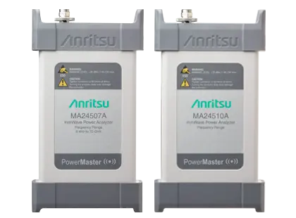
Power Master MA24507A and MA24510A Frequency Selectable mmWave Power Analyzer
USB-powered, frequency selectable mmWave power analyzer that measures signals from 9 kHz to 70 GHz or 110 GHz and down to –90 dBm.
- Frequency Range
- 9 kHz to 70 GHz
- Frequency Range
- 9 kHz to 110 GHz
- Internal Reference Accuracy
- ±0.2 ppm
- Internal Reference Aging
- ±1.0 ppm/year aging
Overview
The Anritsu Power Master is a USB-powered millimeter-wave power analyzer that makes numeric, frequency-selective average power measurements. Two models are available. The MA24507A covers 9 kHz to 70 GHz and the MA24510A covers 9 kHz to 110 GHz. Measurements reach down to –90 dBm, and up to six signals can be measured at once.
Many mmWave sensors are built on thermal components. The Power Master uses a receiver-based architecture instead, which shortens measurement times and makes it frequency selective. Frequency selectivity gives a more accurate power reading in the band of interest. The analyzer is about the size of a smartphone, takes its power from the host's USB connection, and has mounting holes so probes can be attached directly for over-the-air or on-wafer testing.
The Power Master can make stand-alone measurements or work as part of a system, for example when calibrating vector network analyzers.
PowerXpert software
The analyzer is operated from the PowerXpert PC application, which sets the measurement mode, center frequency, span and resolution. In Power Hunter mode, the user defines a frequency range and the software finds the six highest CW amplitudes in it, along with their frequencies. In Channel Monitor mode, up to six frequency channels, each up to 20 MHz wide, are monitored at the same time for CW amplitude or channel power.
Models in this series
| Model | Description | |
|---|---|---|
| MA24507A |
Power Master MA24507A 9 kHz to 70 GHz mmWave Power Analyzer
USB-powered, frequency-selectable mmWave power analyzer covering 9 kHz to 70 GHz with a noise floor as low as –90 dBm. |
Details → |
| MA24510A |
Power Master MA24510A 9 kHz to 110 GHz mmWave Power Analyzer
USB-powered, frequency-selectable mmWave power analyzer covering 9 kHz to 110 GHz with a measurement floor as low as -90 dBm. |
Details → |
Key Features
- Measures low power signals as low as –90 dBm
- Suited to over-the-air testing, especially mmWave signals with high propagation loss
- User settings to control measurement speed and noise floor
- Channel Monitor mode in PowerXpert for monitoring up to six frequency channels at once
- Power Hunter mode in PowerXpert for searching up to six signals within a frequency range
- Mounting holes for direct mounting to probes for over-the-air or on-wafer testing
- Receiver-based architecture for frequency-selective power measurement
- USB-powered, smartphone-sized form factor
Specifications
|
Frequency Range
MA24507A |
9 kHz to 70 GHz |
|---|---|
|
Frequency Range
MA24510A |
9 kHz to 110 GHz
All performance above 70 GHz is Typical |
| Internal Reference Accuracy |
±0.2 ppm
0 °C to 50 °C |
| Internal Reference Aging | ±1.0 ppm/year aging |
| Continuous Mode Span (Channel Power Measurement) | 30 kHz to 2 GHz max |
| Continuous Mode Span (CW Max Measurement) |
10 kHz to Full Span
The PowerXpert section of the datasheet (page 5) lists 1 kHz to Full span (CW max) |
| Channel Monitor Mode Span | 1 kHz to 20 MHz |
| Measurement Range |
-90 — +10 dBm
As stated on the product page |
|---|---|
| Maximum Amplitude (≤ 6.15 GHz) |
+15 dBm
Characteristic |
| Maximum Amplitude (> 6.15 GHz) |
+10 dBm
Characteristic |
| Damage Level |
+30 dBm CW, +/- 10 VDC max
Continuous |
| Range (Lower) |
≤ –10 dBm
User-defined operating range; signals at or below –10 dBm can typically use the lower range |
| Range (Upper) |
> –10 dBm
Upper range recommended for signals above –10 dBm to avoid clipping or saturation |
| Average Noise Floor, Channel Power (30 kHz channel span) |
–88 dBm
Measured at 1GHz center frequency |
| Average Noise Floor, Channel Power (10 MHz channel span) |
–64 dBm
Measured at 1GHz center frequency |
| Average Noise Floor, Channel Power (1 GHz channel span) |
–40 dBm
Measured at 1GHz center frequency |
| Average Noise Floor, CW Max (High resolution) |
–100 dBm
Measured at 1GHz center frequency; 3 MHz span |
| Average Noise Floor, CW Max (Medium resolution) |
–90 dBm
Measured at 1GHz center frequency; 3 MHz span |
| Average Noise Floor, CW Max (Low resolution) |
–80 dBm
Measured at 1GHz center frequency; 3 MHz span |
| Trigger Source | Bus, Continuous |
| 9 kHz to 12.4 GHz | 1.29:1 VSWR, 18 dB return loss |
|---|---|
|
> 12.4 GHz to 26.5 GHz
MA24507A |
1.43:1 VSWR, 15 dB return loss
V connector; the product page lists 1.67 for > 12.4 GHz to 50 GHz |
|
> 12.4 GHz to 26.5 GHz
MA24510A |
1.67:1 VSWR, 12 dB return loss
W1 connector |
|
> 26.5 GHz to 40 GHz
MA24507A |
1.58:1 VSWR, 13 dB return loss
V connector; the product page lists 1.67 for > 12.4 GHz to 50 GHz |
|
> 26.5 GHz to 40 GHz
MA24510A |
1.67:1 VSWR, 12 dB return loss
W1 connector |
| > 40 GHz to 50 GHz | 1.67:1 VSWR, 12 dB return loss |
| > 50 GHz to 70 GHz | 2.10:1 VSWR, 9 dB return loss |
|
> 70 GHz to 110 GHz
MA24510A |
2.10:1 VSWR, 9 dB return loss
W1 connector |
| Channel Power Measurement |
7 (300 kHz span), 20 (20 MHz span), 10 (1 GHz span)
Measured at 1 GHz center frequency; no averages |
|---|---|
| CW Max Measurement (High) |
0.8 (300 kHz span), 15 (20 MHz span), 6 (1 GHz span)
Measured at 1 GHz center frequency; no averages |
| CW Max Measurement (Medium) |
4 (300 kHz span), 25 (20 MHz span), 10 (1 GHz span)
Measured at 1 GHz center frequency; no averages |
| CW Max Measurement (Low) |
20 (300 kHz span), 25 (20 MHz span), 10 (1 GHz span)
Measured at 1 GHz center frequency; no averages |
| Amplitude Accuracy, 9 kHz to 644 MHz |
20 °C to 30 °C: ±1.3 dB max (±0.5 dB typical); 0 °C to 50 °C: ±2.0 dB max (±0.5 dB typical)
Excludes noise and mismatch uncertainty; 30 minute warm-up (20–30 °C), 60 minute warm-up (0–50 °C) |
|---|---|
| Amplitude Accuracy, > 644 MHz to 40 GHz |
20 °C to 30 °C: ±1.8 dB max (±0.5 dB typical); 0 °C to 50 °C: ±3.0 dB max (±1.0 dB typical)
Excludes noise and mismatch uncertainty; the product page lists ±1.0 dB, typical |
| Amplitude Accuracy, > 40 GHz to 70 GHz |
20 °C to 30 °C: ±2.0 dB max (±0.5 dB typical); 0 °C to 50 °C: ±3.0 dB max (±1.0 dB typical)
Excludes noise and mismatch uncertainty; characteristic values between 67 and 70 GHz for MA24507A |
|
Amplitude Accuracy, > 70 GHz to 90 GHz
MA24510A |
20 °C to 30 °C: ±2.2 dB max (±0.5 dB typical); 0 °C to 50 °C: ±3.0 dB max (±1.0 dB typical)
Excludes noise and mismatch uncertainty |
|
Amplitude Accuracy, > 90 GHz to 110 GHz
MA24510A |
20 °C to 30 °C: ±2.5 dB max (±0.5 dB typical); 0 °C to 50 °C: ±3.0 dB max (±1.0 dB typical)
Excludes noise and mismatch uncertainty |
| Relative Power Accuracy, 9 kHz to < 6.15 GHz | ±0.3 dB |
| Relative Power Accuracy, 6.15 GHz to < 40 GHz | ±0.3 dB |
| Relative Power Accuracy, 40 GHz to ≤ 110 GHz |
±0.3 dB
Typical with W1 connector |
| ISO GUM Measurement Uncertainty | Uncertainty expressed with coverage factor of k=2 |
| Software Version | version 4.0 or greater |
|---|---|
| Processor and RAM | Equivalent to Quad Core i5 fourth generation or higher CPU, 8 GB RAM |
| Operating System | Microsoft Windows 10, 8.1, or 7; 64-bit |
| Hard-Disk Free Space | 100 MB minimum |
| Display Resolution | 1024 × 768 minimum |
| Interface | USB 3.0 |
| Measurand | Channel power, CW peak power |
|---|---|
| Measurement Resolution | 0.01 dB max via PowerXpert, 0.01 dB max via remote command |
| Offset Correction |
–100 dB to +150 dB
Available only through the PowerXpert application; no remote command in the analyzer firmware |
| Units | dBm, nW, µW, mW, W |
| Averaging | Manual |
| Averaging Type | Moving |
| Number of Averages | 1 to 1,000 |
| Continuous Mode Measurements | Channel power, CW max |
|---|---|
| Continuous Mode Center Frequency | 9.5 kHz to (Max Freq – 500 Hz) |
| Continuous Mode Span | 30 kHz to 2 GHz (Channel power), 1 kHz to Full span (CW max) |
| Continuous Mode Resolution | High, medium, low |
| Power Hunter Mode Measurement | CW max only |
| Power Hunter Mode Start Frequency | 9 kHz to (Max Freq – 1 kHz) |
| Power Hunter Mode Stop Frequency | 10 kHz to Max Freq |
| Power Hunter Mode Set Minimum Power Range | –130 to 0 dBm |
| Channel Monitor Mode Measurements | Channel power, CW max |
| Channel Monitor Mode Channel Frequencies | (9 kHz + Span/2) to (Max Freq – Span/2) |
| Channel Monitor Mode Span | 1 kHz to 20 MHz |
| Channel Monitor Mode Number of Channels | Up to 6 |
|
RF Connector
MA24507A |
V male (1.85 mm) |
|---|---|
|
RF Connector
MA24510A |
W1 male (1.0 mm)
The product page lists W(m) Connector |
| Trigger Port | Inactive |
| Reference Port | For Service Only |
| Interface to Host |
USB 3.0
USB C port |
| Current Consumption | 900 mA max |
| Size | 155 mm x 84 mm x 27 mm (6.1 in x 3.3 in x 1.1 in) |
| Weight | 282 g (0.62 lb) |
| Warranty | 1 year |
| Warm-Up Time |
30 minutes
Applies to all specifications unless otherwise stated |
| Calibration Cycle |
12 months
Anritsu recommended calibration interval |
| Operational Requirements | Tests were performed per MIL-PRF-28800F (Class 3) |
|---|---|
| Operating Temperature Range | 0 °C to 50 °C |
| Storage Temperature Range | –40 °C to +71 °C |
| Relative Humidity (non-condensing) | 45 % at 50 °C, 75 % at 40 °C, 95 % at 30 °C |
| Altitude | 4600 m operational max |
| Shock | 30 g half-sine, 11 ms duration |
| Vibration (Sinusoidal) | 5 Hz to 55 Hz, 3 g max |
| Vibration (Random) |
10 Hz to 500 Hz, 2.34 g rms
Power Spectral Density: 0.01 g²/Hz |
| European Union EMC | 2014/30/EU, EN 61326:2013, CISPR 11/EN 55011, IEC/EN 61000-4-2/3/4/5/6/8/11 |
|---|---|
| Low Voltage Directive | 2014/35/EU |
| Safety | EN 61010-1:2010 |
| RoHS Directive | 2011/65/EU |
| Australia and New Zealand | RCM AS/NZS 4417:2012 |
| South Korea | KCC-REM-A21-0004 |
Applications
- Over-the-air mmWave testing
- On-wafer testing
- Vector network analyzer calibration systems
- Stand-alone RF and mmWave power measurement
- Antenna quality control for consumer electronics
- Parallel remote power monitoring
Options & Accessories
| Option | Description |
|---|---|
| MA24507A-098/MS24510A-098 | Option 98: Standard calibration ISO/IEC 17025 and ANSI/NCSL Z540-1 |
| MA24507A-099/MS24510A-099 | Option 99: Premium calibration ISO/IEC 17025 and ANSI/NCSL Z540-1 — Includes test report and uncertainty data |
| 01-201 | Calibrated torque wrench for K and V connectors |
| 41VA-3 | Precision Fixed Attenuator, 3 dB, V(m) to V(f) — Precision, DC to 70 GHz, 1W, 3 dB, V(m) to V(f) |
| 41VA-6 | Precision Fixed Attenuator, 6 dB, V(m) to V(f) — Precision, DC to 70 GHz, 1W, 6 dB, V(m) to V(f) |
| 41VA-10 | Precision Fixed Attenuator, 10 dB, V(m) to V(f) — Precision, DC to 70 GHz, 1W, 10 dB, V(m) to V(f) |
| 41VA-20 | Precision Fixed Attenuator, 20 dB, V(m) to V(f) — Precision, DC to 70 GHz, 1W, 20 dB, V(m) to V(f) |
| 41W-3 | Precision Fixed Attenuator, 3 dB, W1(m) to W1(f) — Precision, DC to 110 GHz, 1W, 3 dB, W1(m) to W1 (f) |
| 41W-6 | Precision Fixed Attenuator, 6 dB, W1(m) to W1(f) — Precision, DC to 110 GHz, 1W, 6 dB, W1(m) to W1 (f) |
| 41W-10 | Precision Fixed Attenuator, 10 dB, W1(m) to W1(f) — Precision, DC to 110 GHz, 1W, 10 dB, W1(m) to W1 (f) |
| W240A | Precision Power Divider — Precision, DC to 110 GHz, 3 resistor, W1(f) input, W1(f) output |
| W241A | Precision Power Splitter — Precision, DC to 110 GHz, 2 resistor, W1(m) input, W1(f) output |
| MN25110A | Precision Directional Coupler — Precision, 20 GHz to 110 GHz, W1(f) input, W1(f) output, W1(f) coupled port |
| 33VFVF50C | Precision Coaxial Adapter, V(f) to V(f) — DC to 70 GHz, V(f) to V(f), 50 Ω |
| 33VVF50C | Precision Coaxial Adapter, V(m) to V(f) — DC to 70 GHz, V(m) to V(f), 50 Ω |
| 34WFV50 | Precision Coaxial Adapter, W1(f) to V(m) — DC to 65 GHz, W1(f) to V(m), 50 Ω |
| 34WFVF50 | Precision Coaxial Adapter, W1(f) to V(f) — DC to 65 GHz, W1(f) to V(f), 50 Ω |
| 34WV50 | Precision Coaxial Adapter, W1(m) to V(m) — DC to 65 GHz, W1(m) to V(m), 50 Ω |
| 33WFWF50 | Precision Coaxial Adapter, W1(f) to W1(f) — DC to 110 GHz, W1(f) to W1(f), 50 Ω |
| 33WW50 | Precision Coaxial Adapter, W1(m) to W1(m) |
| 33WWF50 | Precision Coaxial Adapter, W1(m) to W1(f) |
| 35WR22VF | Waveguide to Coaxial Adapter (right angle), WR22 to V(f) — 33 GHz to 50 GHz, WR22 to V(f) |
| 35WR19VF | Waveguide to Coaxial Adapter (right angle), WR19 to V(f) — 40 GHz to 60 GHz, WR19 to V(f) |
| 35WR15VF | Waveguide to Coaxial Adapter (right angle), WR15 to V(f) — 50 GHz to 65 GHz, WR15 to V(f) |
| 35WR10WF | Waveguide to Coaxial Adapter (right angle), WR10 to W1(f) — 75 GHz to 110 GHz, WR10 to W1(f) |
| SC7442 | Waveguide to Coaxial Adapter (right angle), WR12 to W1(f) — 60 GHz to 90 GHz, WR12 to W1(f) |
| 1091-400-R | Waveguide to Coaxial End Launch Adapter, WR10 to W1(f) — 73.8 GHz to 110 GHz, WR10 to W1(f) |
| 1091-401-R | Waveguide to Coaxial End Launch Adapter, WR12 to W1(f) — 60.5 GHz to 92.0 GHz, WR12 to W1(f) |
| 1091-402-R | Waveguide to Coaxial End Launch Adapter, WR15 to W1(f) — 49.9 GHz to 75.8 GHz, WR15 to W1(f) |
| 1091-456-R | Waveguide to Coaxial End Launch Adapter, WR15 to V(f) — 49.9 GHz to 67.0 GHz, WR15 to V(f) |
| 1091-457-R | Waveguide to Coaxial End Launch Adapter, WR19 to V(f) — 39.3 GHz to 59.7 GHz, WR19 to V(f) |
| 1091-458-R | Waveguide to Coaxial End Launch Adapter, WR22 to V(f) — 33.0 GHz to 50.1 GHz, WR22 to V(f) |
| 1091-459-R | Waveguide to Coaxial End Launch Adapter, WR28 to V(f) — 26.4 GHz to 40.1 GHz, WR28 to V(f) |
| 2000-1867-R | Directional Horn Antenna, WR42 — 17.6 GHz to 26.7 GHz, WR42, 25 dBi gain |
| 2000-1868-R | Directional Horn Antenna, WR28 — 26.4 GHz to 40.1 GHz, WR28, 25 dBi gain |
| 2000-1869-R | Directional Horn Antenna, WR22 — 33.0 GHz to 50.1 GHz, WR22, 25 dB gain |
| 2000-1870-R | Directional Horn Antenna, WR19 — 39.3 GHz to 59.7 GHz, WR19, 25 dBi gain |
| 2000-1871-R | Directional Horn Antenna, WR15 — 49.9 GHz to 75.8 GHz, WR15, 25 dBi gain |
| 2000-1872-R | Directional Horn Antenna, WR12 — 60.0 GHz to 90.0 GHz, WR12, 25 dBi gain |
| 2000-1873-R | Directional Horn Antenna, WR10 — 75.0 GHz to 110.0 GHz, WR10, 25 dBi gain |
| 2000-1888-R | USB 3.0 Powered Extension Cable, 10 m, (32 ft) — Up to two can be used in series for a total length of 20 m |