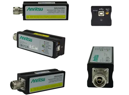
MA24400A Series MA24419A USB Peak Power Sensor, 50 MHz to 18 GHz
USB peak power sensor covering 50 MHz to 18 GHz with -50 dBm to +20 dBm average dynamic range and 6 MHz video bandwidth.
- Frequency Range
- 50 MHz to 18 GHz
- Dynamic Range (Average)
- -50 dBm to +20 dBm
- Dynamic Range (Pulse)
- -40 dBm to +20 dBm
- Input Damage Level
- +23 dBm, ±10.0 VDC (+30 dBm peak for 1 µs)
Overview
The Anritsu MA24419A is a microwave peak power sensor in the MA24400A (MA244xxA) USB Peak Power Sensor series. It covers 50 MHz to 18 GHz with an N(m) RF connector and connects directly to a PC over USB 2.0 high speed. Its average power dynamic range is -50 dBm to +20 dBm, and its pulse dynamic range is -40 dBm to +20 dBm.
Within the series, the MA24419A pairs a 6 MHz fast video bandwidth with the wider dynamic range. The MA24418A covers the same frequency range with a wider video bandwidth and a narrower dynamic range. The sensor also offers a 350 kHz standard video bandwidth for average-power measurements.
Measurement architecture
The series processes power readings in parallel, in real time. The sensor keeps measuring while it handles captured data, so re-arm gaps are minimal. Sampling runs at 100 MSa/s continuous and 10 GSa/s effective, and the sensor makes up to 100,000 measurements per second. Triggering can be continuous, internal, external TTL through an SMB input, or crossover from another sensor, which allows synchronized multi-channel measurements.
Software
The supplied PC software, Microwave Peak Power Analyzer, sets up the sensor and displays results. Its views include peak and average power readouts, a trace view for pulse power analysis, and CCDF graphs for crest factor and statistical measurements.
Key Features
- 50 MHz to 18 GHz frequency range
- -50 dBm to +20 dBm average dynamic range
- 6 MHz fast video bandwidth, 350 kHz standard video bandwidth
- 100,000 measurements per second
- Real-time processing of power readings
- 100 MS/s continuous and 10 GS/s effective sampling rates
- Full pulse profiling
- Crest factor, CCDF and statistical measurements
- Synchronized multi-channel measurements
- Microwave Peak Power Analyzer measurement and analysis software
- USB 2.0 high speed interface to host PC
Specifications
| Frequency Range | 50 MHz to 18 GHz |
|---|---|
| Dynamic Range (Average) | -50 dBm to +20 dBm |
| Dynamic Range (Pulse) | -40 dBm to +20 dBm |
| Input Damage Level |
+23 dBm, ±10.0 VDC (+30 dBm peak for 1 µs)
minimum
|
| Maximum Input |
200 mW (+23 dBm) average, 1 W (+30 dBm) peak for 1 μs, ±10.0 VDC
Warning marked on sensor
|
| VSWR, 50 MHz to 2 GHz | 1.15:1 |
|---|---|
| VSWR, >2.0 GHz to 6 GHz | 1.20:1 |
| VSWR, >6.0 GHz to 16 GHz | 1.28:1 |
| VSWR, >16 GHz to 18 GHz | 1.34:1 |
| Sampling Rate |
100 MSa/s
characteristic
|
|---|---|
| Effective Sampling Rate |
10 GSa/s
characteristic
|
| Single Channel Rise Time (Fast) | <100 ns |
| Single Channel Rise Time (Standard) | <10 µs |
| Video Bandwidth (Fast) | 6 MHz |
| Video Bandwidth (Standard) | 350 kHz |
| Single Shot Bandwidth | 6 MHz |
| Minimum Pulse Width Dynamic Range | -27 dBm to +20 dBm |
| Minimum Pulse Width (Fast) | 200 ns |
| Minimum Pulse Width (Standard) | 3 µs |
| Source | Continuous, Internal, External TTL, Crossover (from another sensor) |
|---|---|
| Arm Type | Continuous, Single, Trigger Holdoff, Frame (gap) Holdoff |
| Slope | Positive or Negative |
| Trigger Hold Off | 100 ns to 1 s with 10 ns resolution |
| External Trigger Input | SMB (female) |
|---|---|
| Impedance | 10 kΩ |
| Type | TTL |
| High Level Input Voltage | 2.4 V min, 5.5 V max |
| Low Level Input Voltage | -0.1 V min, 0.7 V max |
| Latency |
< 10 ns
Latency is defined as the time delay between the defined edge of the applied trigger and the sensor switching into the triggered state.
|
| Trigger Pulse Width | 10 ns min |
| Trigger Repetition Period | 20 ns min |
| Processor | 1.3 GHz or higher recommended |
|---|---|
| RAM | 512 MB (1 GB or more recommended) |
| Operating System | Microsoft Windows 7 to 10 (32-bit and 64-bit) |
| Hard-Disk Free Space | Min 1.0 GB free space to install and run |
| Display Resolution | 800 x 600 (1280 x 1024 or higher recommended) |
| Interface | USB 2.0 high speed |
| Interface to Host | USB 2.0 high speed |
|---|---|
| RF Connector |
N(m)
Datasheet: N male to 20 GHz
|
| Size | 145 mm x 43 mm x 43 mm, excluding N connector |
| Weight | 363 g (0.80 lb) |
| Connector Torque |
90 N·cm (8 lbf·in)
Do not rotate sensor body to connect or disconnect.
|
| Warm-Up Time | 60 minutes |
| Calibration Cycle |
12 months
Anritsu recommended calibration interval
|
| Warranty | 1 year from the date of shipment |
| Test Standard | MIL-28800F (Class3) |
|---|---|
| Operating Temperature Range | 0 ºC to 55 ºC |
| Storage Temperature Range | -40 ºC to +70 ºC |
| Relative Humidity (non-condensing) | 45 % at 50 ºC, 75 % at 40 ºC, 95 % at 30 ºC |
| Altitude | 3048 m operational max |
| Shock | 30 g half-sine, 11 ms duration |
| Vibration | Sinusoidal: 5 Hz to 55 Hz, 3 g max; Random: 10 Hz to 500 Hz, 2.34 g rms; Power Spectral Density: 0.01 g²/Hz |
| EMC Directive |
2014/30/EU, EN 61326:2013
European Union
|
|---|---|
| Emissions | CISPR 11/EN 55011:2019+A1:2010 Class A Equipment |
| Immunity | IEC/EN 61000-4-2/3/4/6 |
| Low Voltage Directive | 2014/35/EU, EN 61010-1:2001 |
| RoHS Directive | 2015/863/EU |
Specifications are taken from the manufacturer's documentation. See the datasheet for complete and current values.
Applications
- Radar systems
- Pulsed communication
- Aerospace and defense
- Electronic warfare system testing
- Component testing
- High-power microwave (HPM) applications
- Wideband modulated signal measurement
Included
- 11410-00976 Information Card
- 806-391-R 1.8 m USB A (m) to USB B (m) cable
Options & Accessories
| Option | Description |
|---|---|
| MA24419A-097 | Accredited Calibration to ISO/IEC 17025 and ANSI/NCSL Z540-1 or ANSI/NCSL Z540.3 — Includes test report, uncertainty data, and accreditation symbol |
| 3-1010-122 | Attenuator, 20 dB, 5 W, DC to 12.4 GHz, N(m) to N(f) |
| 42N50-20 | Attenuator, 20 dB, 5 W, DC to 18 GHz, N(m) to N(f) |
| 3-1010-123 | Attenuator, 30 dB, 50 W, DC to 8.5 GHz, N(m) to N(f) |
| 42N50A-30 | Attenuator, 30 dB, 50 W, DC to 18 GHz, N(m) to N(f) |
| 3-1010-124 | Attenuator, 40 dB, 100 W, DC-8.5 GHz, N(f) input to N(m) output, Unidirectional |
| 34NFK50 | Precision Adapter, DC to 18 GHz, N(f) to K(m), 50Ω |
| 34NK50 | Precision Adapter, DC to 18 GHz, N(m) to K(m), 50Ω |
| 34NKF50 | Precision Adapter, DC to 18 GHz, N(m) to K(f), 50Ω |
| 33NFNF50B | Calibration Grade Adapter, DC to 18 GHz, N(f) to N(f), 50Ω |
| 33NNF50B | Calibration Grade Adapter, DC to 18 GHz, N(m) to N(f), 50Ω |
| 34NN50A | Calibration Grade Adapter, DC to 18 GHz, N(m) to N(m), 50Ω |
| 1091-26-R | Adapter, SMA(m) to N(m), DC to 18 GHz, 50Ω |
| 1091-27-R | Adapter, SMA(f) to N(m), DC to 18 GHz, 50Ω |
| 1091-80-R | Adapter, SMA(m) to N(f), DC to 18 GHz, 50Ω |
| 1091-81-R | Adapter, SMA(f) to N(f), DC to 18 GHz, 50Ω |
| 510-90-R | Adapter, 7/16 DIN(f) to N(m), DC to 7.5 GHz, 50Ω |
| 510-91-R | Adapter, 7/16 DIN(f) to N(f), DC to 7.5 GHz, 50Ω |
| 510-92-R | Adapter, 7/16 DIN(m) to N(m), DC to 7.5 GHz, 50Ω |
| 510-93-R | Adapter, 7/16 DIN(m) to N(f), DC to 7.5 GHz, 50Ω |
Documents & Resources
Related Products
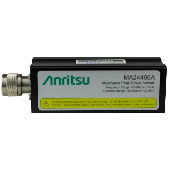
USB peak power sensor covering 50 MHz to 6 GHz with 195 MHz video bandwidth, 3 ns rise time and –60 dBm to +20 dBm average dynamic range.
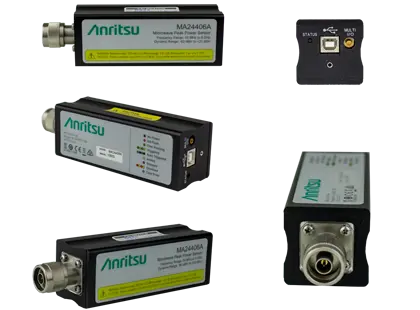
USB peak power sensor covering 50 MHz to 8 GHz with up to 165 MHz video bandwidth and 4 ns rise time.
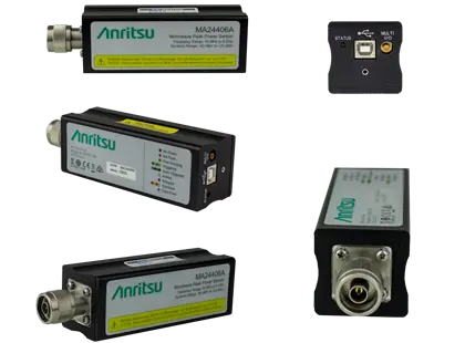
USB peak power sensor covering 50 MHz to 18 GHz with 70 MHz video bandwidth and 5 ns rise time for pulse and modulated signals.
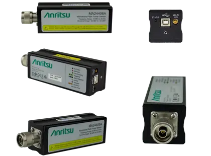
USB microwave peak power sensor covering 50 MHz to 40 GHz with 70 MHz video bandwidth, 5 ns rise time and a K(m) connector.
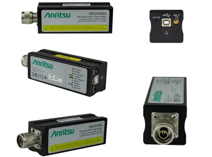
USB peak power sensor covering 50 MHz to 40 GHz with -50 dBm to +20 dBm average dynamic range and a K(m) connector.