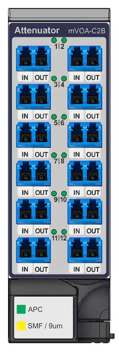
VIAVI MAP Series mVOA-C2B MVOA-C2B08-SB0-M100-MLC 8-Channel Variable Optical Attenuator Module, LC/PC
MEMS-based 8-device variable optical attenuator module for the MAP-300 platform, no power monitors, singlemode LC/PC connectors.
- Configuration
- No Monitor
- Number of Channels
- 8
- Connector
- LC/PC
Overview
The MVOA-C2B08-SB0-M100-MLC is the 8-device, no-monitor, LC/PC version of the VIAVI MAP Series mVOA-C2B high-density variable optical attenuator. The ordering information describes it as MAP Series VOA B-type 8 devices no option SMF LC/PC. The module uses a MEMS mirror design and is built for programmable attenuation in lab and production test.
The mVOA-C2B is a hot-pluggable, single-slot cassette for the VIAVI MAP ecosystem and works with all MAP-300 generation mainframes. Up to eight modules fit in one 3U MAP-300 mainframe, so a fully loaded chassis can hold up to 96 independently controlled attenuators when 12-device modules are used. It follows the earlier mVOA-C1 attenuator.
Operating mode
This no-monitor variant runs in Attenuator Mode. The user enters the desired attenuation through the user interface or a remote SCPI command, and the module sets the output attenuation directly in open loop. Constant Power Mode and IL Mode need the in/out monitor variants (SB1).
Applications
The datasheet lists client optic testing, next-generation coherent interfaces, long-haul network stress testing and silicon photonics development as uses. The wide wavelength range covers CWDM and DWDM work, and the high input power capability suits EDFA and multi-wavelength testing.
Key Features
- MEMS mirror-based programmable optical attenuation
- 8 independently controlled attenuator devices in one module
- Singlemode fiber LC/PC connectors
- Single-slot, hot-pluggable module for all MAP-300 generation mainframes
- Up to 96 attenuators in a single 3U MAP-300 mainframe
- Low insertion loss, return loss and polarization dependent loss
- High accuracy and repeatability
- Fast transition speed and settling time
- Flat spectral response for CWDM and DWDM applications
- Low backreflection
- High input power capability for EDFA testing and multi-wavelength applications
- Attenuation control from the UI or remote SCPI commands
Specifications
| Configuration | No Monitor |
|---|---|
| Number of Channels |
8
Series available with 4, 8, 12
|
| Connector |
LC/PC
SMF; series available with LC/PC and LC/APC
|
| Wavelength Range |
1260 to 1640 nm
All optical measurements taken after minimum 30-minute warm up; measured at constant temperature of 23 ±5°C
|
|---|---|
| Insertion Loss |
<=1.6 dB
No Monitor configuration
|
| Attenuation Range | > 40 dB |
| Return Loss | 40 dB min/55 dB typ |
| Shutter Isolation | > 45 dB |
| Maximum Optical Input Power |
27 dBm
No Monitor configuration
|
| Repeatability | ±0.05 dB (typ.), 0 dB to 30 dB; ±0.10 dB (typ.), 30 dB to 40 dB |
|---|---|
| Relative Attenuation Accuracy |
±0.15 dB (typ.), 0 dB to 10 dB; ±0.15 dB (typ.), 10 dB to 20 dB; ±0.20 dB (typ.), 10 dB to 20 dB
As printed in the datasheet; the 10 dB to 20 dB range appears twice with different values
|
| PDL | < 0.15 dB, at 0 dB; < 0.30 dB, 0 dB to 10 dB; < 0.50 dB, 10 dB to 20 dB |
| Attenuation Speed | 0.1 dB/s to 1000 dB/s |
|---|---|
| MAP Command Latency | < 1 ms |
| Activation Latency | < 500 μs |
| Trigger Latency | < 10 μs |
| Warm-up Time | 30 min |
|---|---|
| Slot Width | 1 standard module |
| Calibration Period | 1 Year |
| Operating Temperature |
10 °C to 40 °C
Requirement
|
| Storage Temperature | -30°C to 60°C |
| Compatible Mainframes |
All MAP-300 generation mainframes
Up to eight modules in a single MAP-300 mainframe
|
Specifications are taken from the manufacturer's documentation. See the datasheet for complete and current values.
Applications
- Network emulation test systems
- Client optic testing
- Next generation coherent interfaces
- Long haul network stress testing
- Silicon photonics development
- EDFA testing
- CWDM and DWDM applications
- Lab and production test
Options & Accessories
| Option | Description |
|---|---|
| CleanBlastPRO | CleanBlastPRO fiber end-face cleaning system — Optional inspection and cleaning tool for removing dirt and debris from connectors. |
| FiberChek | FiberChek probe microscope — Optional one-button handheld fiber inspection probe. |