VIAVI mORL-A1 MORL-A11308-BID-M101-MFA Multimode Bidirectional IL/RL Meter Module for MAP-Series
Multimode 850/1300 nm IL/RL meter module for the MAP-Series with 50 µm OM3 fiber, bidirectional testing and FC/APC output.
- Description
- IL/RL meter 850/1300nm 50um OM3 MMF Bidirectional FC/APC
- Bidirectional option
- Internal 2x2 switch
Overview
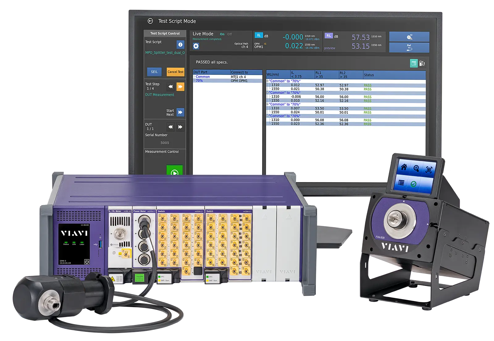
The MORL-A11308-BID-M101-MFA is the multimode, bidirectional version of the VIAVI mORL-A1 insertion loss (IL) and return loss (RL) meter. VIAVI describes it as an IL/RL meter at 850/1300 nm for 50 µm OM3 multimode fiber with an FC/APC interface. The module installs in a MAP-Series chassis and is the core measurement module of the VIAVI Passive Component/Connector Test solution (PCT). PCT is used to test insertion loss, return loss, physical length and polarity of optical connectors, cable assemblies, structured cabling and splitters.
Measurement principle
The multimode module uses the same technology and architecture as the single-mode mORL-A1. It combines dual-wavelength sources with an integrated power meter. IL is measured with the power meter method, and multimode IL meets the IEC 61280-4-1 Encircled Flux requirements. Users can choose laser or low-power LED sources in software. The LED sources have lower coherence, which reduces speckle-related instability at the power meter. RL is measured with time-domain (mandrel-free) technology, in parallel with IL, using the same optical stimulus.
Bidirectional testing
The BID code adds an internal 2x2 switch to the module. Combined with the time-domain RL measurement and its programmable window function, the module can measure RL on both connectors of a jumper with a single connection, so the jumper does not need to be re-measured in the other direction. The bidirectional test can also be used on hybrid assemblies.
Software and system integration
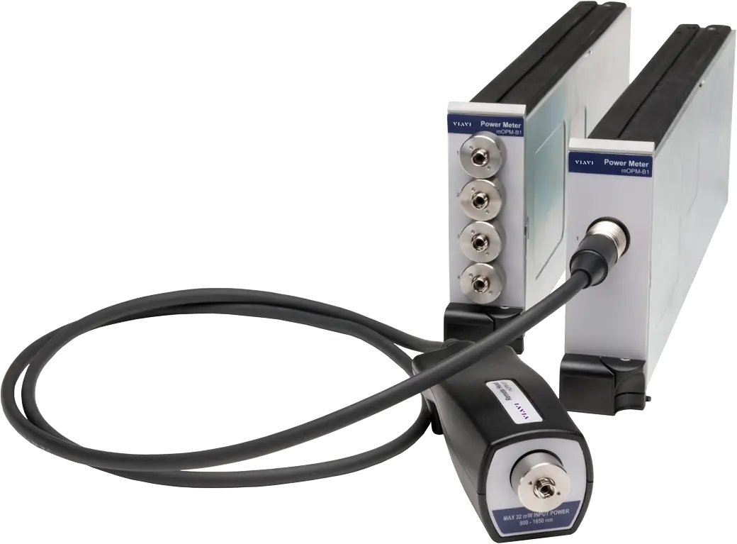
The module runs under the PCT application (PCT Max or PCT Lite), which offers instrument mode, script (DUT aware) mode with database storage, and port mapping, along with a full SCPI command set over LAN or GPIB. It is often used with the MAP optical switch (mOSW) and remote optical power meter (mOPM) modules, which add channels, remote heads and polarity measurement.
Key Features
- Multimode IL/RL meter at 850/1300 nm for 50 µm OM3 fiber
- Bidirectional version with internal 2x2 optical switch
- FC/APC connector interface
- LED or laser source modes, software selectable
- IL display resolution of 0.001 dB
- Mandrel-free time-domain RL measurement performed in parallel with IL
- Multimode IL meets IEC 61280-4-1 Encircled Flux requirements
- Small footprint - 25% of competing solutions
- Integrated automation via SCPI and no-code scripting
- Database interface and report generation
- MPO and MTP capable with simultaneous polarity measurement
- Growth enabling - 1 to 1,000+ DUT channels
- Port mapping verifies multifiber MPO cassette continuity and polarity in less than 15 seconds
Specifications
| Description | IL/RL meter 850/1300nm 50um OM3 MMF Bidirectional FC/APC |
|---|---|
| Bidirectional option |
Internal 2x2 switch
The BID code option adds an internal 2x2 switch to the mORL module
|
| 2-Wavelength Version |
850, 1300 nm
Multimode mORL-A1
|
|---|
| Single Fiber |
50 µm core (OM3)
Multimode mORL-A1
|
|---|
| Initializing Time | < 4s |
|---|---|
| Averaging Options Per Wavelength |
0.5, 1, 2, 5, 10s
The MAP-Based IL/RL Testing Solution data sheet lists 2, 5, 10s
|
| Total Time (IL, RL, Polarity) for 2 wavelengths |
23s (12 channels), 44s (24 channels)
With mOPM-C1RHPM Remote Head Polarity Mapper
|
| Concurrent IL and RL measurement |
less than 2s per wavelength
Multimode module
|
| Modes | LED or laser (software selectable) |
|---|---|
| Display Resolution | 0.001 dB |
| Total IL Uncertainty |
± 0.05 dB
After valid zero loss, total expanded uncertainty (2σ), reconnecting the same connector and OPM adaptor, temperature ±1°C, using internal source (also for LED mode); IL uncertainty from launching condition is not included
|
| Additional Uncertainties Due to 1xN Switching (if mOSW-C1 added) | ± 0.01 dB |
| Additional Uncertainties Due to Fiber Position in the Integrating Sphere |
± 0.03 dB
24-channel ribbon fiber
|
| IL stability |
±0.02 dB
Launch powers monitored
|
| Display Resolution | 0.01 dB |
|---|---|
| RL measurement range |
15 to 60 dB
Multimode module, during concurrent IL measurements
|
| DUT length, DUT reflections (both ends) < 40 dB | > 170 cm |
| DUT length, DUT reflections (both ends) > 40 dB | > 70 cm |
| Return Loss Repeatability (15 to 60 dB) |
± 0.2 dB
Multimode; 5 s averaging time and 200 m range; 10 measurements with a stable connection of a 3 m patch cord
|
| Return Loss Repeatability (60 to 70 dB) |
± 0.5 dB
Multimode; 5 s averaging time and 200 m range; 10 measurements with a stable connection of a 3 m patch cord
|
| Return Loss Accuracy (15 to 20 dB) |
± 1.8 dB
Multimode; 5 s averaging time and 200 m range
|
| Return Loss Accuracy (20 to 60 dB) |
± 1.3 dB
Multimode; 5 s averaging time and 200 m range
|
| Recalibration Period | 1 year |
| Warm-up Time | 20 min |
|---|---|
| Operating Temperature, Humidity | 25 ± 5°C non-condensing humidity |
| Storage Temperature | - 30 to + 60°C |
| Size (W x H x D) | 4.06 x 13.26 x 37.03 cm (1.6 x 5.22 x 14.58 in) |
|---|---|
| Weight (Approximately) | 1.2 kg (2.65 lb) |
| Safety and interface |
CE, CSA/UL/IEC61010-1, and LXI Class C
MAP mORL-A1 modules installed in a MAP Series chassis
|
|---|---|
| Multimode IL | Meets IEC 61280-4-1 Encircled Flux requirements |
Specifications are taken from the manufacturer's documentation. See the datasheet for complete and current values.
Applications
- IL, RL and length testing of optical connectors and cable assemblies
- Structured-cabling solutions and optical splitters
- Multimode fiber-based device testing
- Automated testing of multifiber assemblies such as MPO
- Verifying continuity and polarity of large multifiber assemblies
- Measuring RL of line cards and receptacle-based transponders
Options & Accessories
| Option | Description |
|---|---|
| MSUP-300A-FIT | MAP-300 fiber connector inspection app — Requires probe |
| MSUP-300A-PCTMAPPING | MAP-300 PCT polarity and port mapping application add-on |
| MSUP-300A-PCTREMDB | MAP-300 PCT remote centralized database connection key |
| MSUP-300A-SBSC | MAP-300 PCT driver for legacy SB/SC series switches |
| MSUP-300A-PCT-TDR | MAP-300 Enhanced PCT TDR License |
| MSUP-300A-PCTCASCADE | MAP-300 PCT Switch Cascade |
| MSUP-300A-PCTLOGGING | MAP-300 PCT Continuous Mode Logging License |
| MSUP-300A-SEIL | MAP-300 Single Ended Insertion Loss license |
| MSUP-FIT | MAP-200 Super Application Fiber Inspection (FIT) |
| MSUP-PCTMAPPING | MAP-200 Super Application PCT Mapping |
| MSUP-PCTREMDB | MAP-200 CT Remote Database Connection Key |
| MSUP-SBSC | MAP-200 driver for legacy SB/SC series switches |
| MOSW-C111C004B0-MXXX-MYY | Single 1 x 4 switch, bulkheads — XXX defines fiber type (M101 = 50 µm (OM3)), YY defines connector type (MFA = FC/APC) |
| MOSW-C111C008B0-MXXX-MYY | Single 1 x 8 switch, bulkheads |
| MOSW-C111C012B0-MXXX-MYY | Single 1 x 12 switch, bulkheads (Dual width module) |
| MOSW-C111C024B0-MXXX-MYY | Single 1 x 24 switch, bulkheads (Dual width module) |
| MOPM-C1RH1 | Single channel remote interface cassette |
| MOPM-C1RH2 | Dual channel remote interface cassette |
| MOPM-C1RH4 | Quad channel remote interface cassette |
| MOPM-C1RHPCT | 2mm InGaAs PCT system remote head |
| MOPM-C1RHIP | Integrated PCT system remote head |
| MOPM-C1RHPM | Remote Head Polarity Mapper — Requires MAP-300 FW 13.0+ with PCT and MOPM-C1RH1 base cassette |
| AC500 | FC/PC-FC/PC Universal Connector Adapter — Replacement mating sleeve |
| AC501 | FC/PC-SC/PC Universal Connector Adapter — Replacement mating sleeve |
| AC502 | FC/APC-FC/APC Universal Connector Adapter — Replacement mating sleeve |
| AC503 | FC/APC-SC/APC Universal Connector Adapter — Replacement mating sleeve |