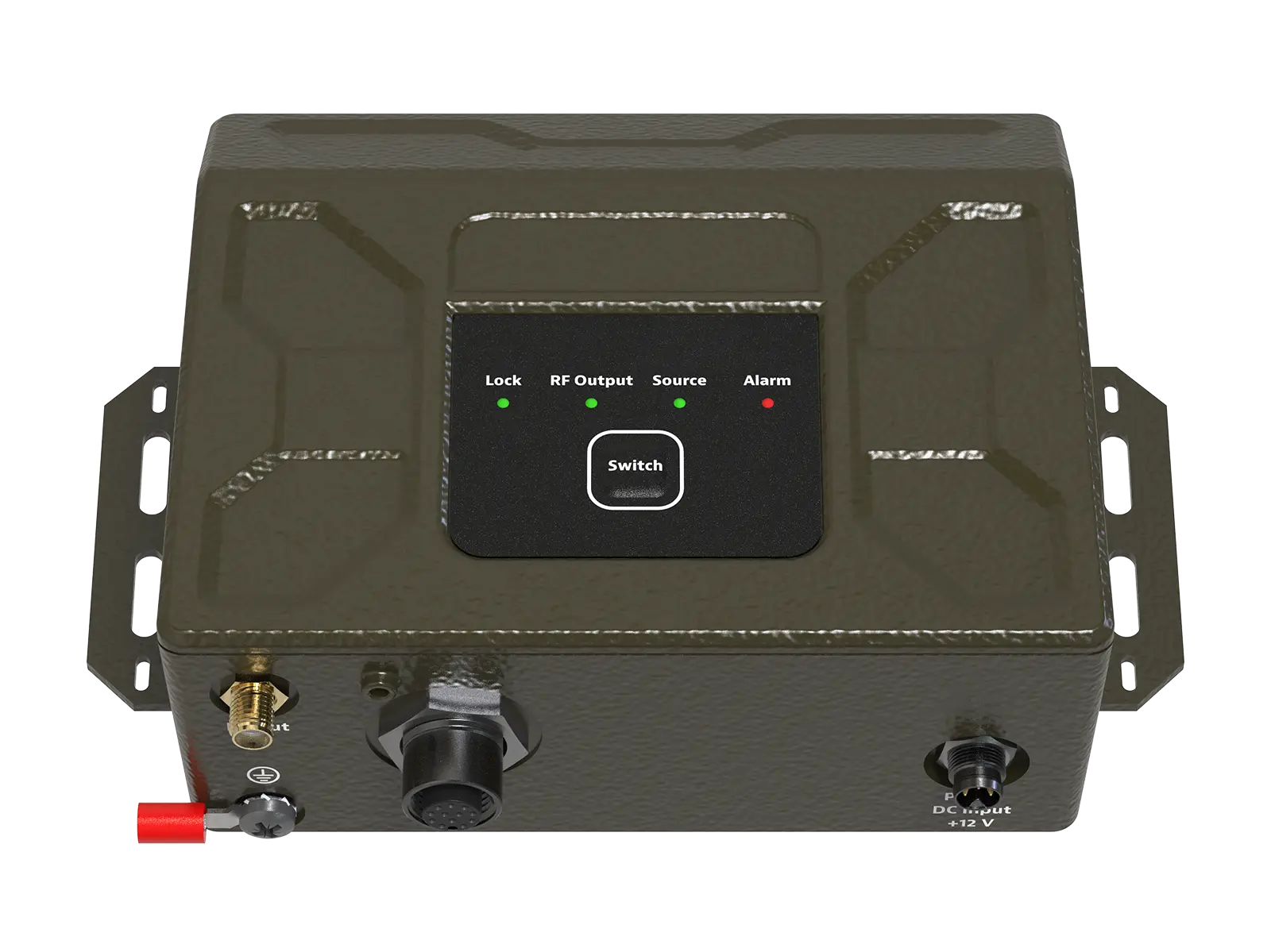
VIAVI RSR Transcoder 2.0 Assured PNT to Legacy GPS RF Transcoder
Rugged real-time transcoder that converts M-Code, SAASM, INS and other PNT inputs into legacy-compatible GPS L1/L2 RF signals.
- Output Frequency
- GPS L1 (1575.42 MHz), L2 (1227.6 MHz)
- Code Type
- GPS L1 C/A, L1 and L2 P-code
- Power Level
- -100 to -120 dBm
Overview
Electronic warfare is increasingly used to jam and spoof the Global Positioning System, which makes reliable navigation and timing difficult in GPS/GNSS denied, degraded and disrupted space operational environments (D3SOE).
The VIAVI RSR Transcoder 2.0 is a rugged, real-time system that converts modern Assured PNT inputs such as M-Code, SAASM, INS and other signals of opportunity into legacy-compatible GPS RF signals. It is based on a patented methodology and includes a full-constellation GPS simulator that outputs standard GPS L1 C/A, L1 P-code and L2 P-code signals.
Legacy integration
The Transcoder generates a GPS RF signal at configurable power levels that the legacy receiver sees as a live-sky signal. Legacy systems can therefore be upgraded by replacing the GPS antenna with the Transcoder, without changes to the receiver's internal hardware or software.
The unit accepts NMEA Position, Velocity and Time (PVT) inputs and processes them within milliseconds, so modern PNT sources such as M-code, SAASM, SBAS, Galileo, GLONASS and BeiDou can be converted into signals usable by GB-GRAM, MicroGRAM, DAGR and similar receivers.
Software options
The 100 Hz Refresh option raises the accepted PVT input rate and the internal simulation and RF output rate to 100 Hz, for airborne, missile and high-speed vehicle platforms where 1 Hz or 10 Hz updates are not sufficient. The ICD-GPS-153 Interface option lets the Transcoder 2.0 configure ICD-GPS-153-compatible receivers such as the DAGR and retrieve real-time data from them, including the Time Mark (8504) message, live almanac, ephemeris and UTC corrections.
The family comes as bare modules and as variants in an IP67 enclosure, with internal oscillator choices that include CSAC, TCSAC and MEMS.
Models in this series
| Model | Description | |
|---|---|---|
| RSR-T2000 |
RSR Transcoder 2.0 RSR-T2000 GPS RF Transcoder Module
Board-level RSR Transcoder 2.0 module that converts M-Code, SAASM, INS and NMEA PNT inputs into legacy GPS L1/L2 RF signals. |
Details → |
| RSR-T2010 |
RSR Transcoder 2.0 RSR-T2010 GPS RF Transcoder Module with CSAC
Board-level RSR Transcoder 2.0 module with CSAC that converts M-Code, SAASM, INS and NMEA PNT inputs into legacy GPS L1/L2 RF signals. |
Details → |
| RSR-T2020 |
RSR Transcoder 2.0 RSR-T2020 GPS RF Transcoder Module with TCSAC
Board-level RSR Transcoder 2.0 module with TCSAC that converts M-Code, SAASM, INS and NMEA PNT inputs into legacy GPS L1/L2 RF signals. |
Details → |
| RSR-T2030 |
RSR Transcoder 2.0 RSR-T2030 GPS RF Transcoder Module with MEMS
Board-level RSR Transcoder 2.0 module with MEMS that converts M-Code, SAASM, INS and NMEA PNT inputs into legacy GPS L1/L2 RF signals. |
Details → |
| RSR-T2100 |
RSR Transcoder 2.0 RSR-T2100 GPS RF Transcoder with IP67 Enclosure
RSR Transcoder 2.0 in an IP67 enclosure that converts M-Code, SAASM, INS and NMEA PNT inputs into legacy GPS L1/L2 RF signals. |
Details → |
| RSR-T2110 |
RSR Transcoder 2.0 RSR-T2110 GPS RF Transcoder with CSAC and IP67 Enclosure
RSR Transcoder 2.0 with CSAC in an IP67 enclosure, converting M-Code, SAASM, INS and NMEA PNT inputs into legacy GPS L1/L2 RF signals. |
Details → |
| RSR-T2130 |
RSR Transcoder 2.0 RSR-T2130 GPS RF Transcoder with MEMS and IP67 Enclosure
RSR Transcoder 2.0 with MEMS in an IP67 enclosure, converting M-Code, SAASM, INS and NMEA PNT inputs into legacy GPS L1/L2 RF signals. |
Details → |
Key Features
- Generates GPS L1 C/A, L1 and L2 P-code RF signals compatible with legacy receivers
- Full-constellation GPS simulator built in
- Update rates up to 100 Hz
- External 1PPS input enables time-transfer accuracy better than 5 nanoseconds
- Automatic detection and configuration of BAE Systems (DAGR, MicroGRAM) and u-blox receivers
- Supports ICD-GPS-153 from military user equipment
- Accepts NMEA Position, Velocity and Time (PVT) inputs processed within milliseconds
- Configurable RF output power level that appears to the receiver as a live-sky signal
- Designed for vehicle, airborne and portable deployments
- Supports covert or lights-out operation for tactical scenarios
- Background monitoring of RF output power and RF signal quality
Specifications
| Output Frequency | GPS L1 (1575.42 MHz), L2 (1227.6 MHz) |
|---|---|
| Code Type | GPS L1 C/A, L1 and L2 P-code |
| Power Level | -100 to -120 dBm |
| In-Band Spurious |
< -33 dBc
L1, ±20 MHz |
|---|---|
| Out-of-Band Spurious | < -80 dBm |
| Harmonics of L1 | < -150 dBm |
| Monitoring Functions | Background monitoring of RF output power and RF signal quality |
|---|
| Compatible Sources | Any source that outputs NMEA |
|---|---|
| Direct Receiver Control |
Rockwell Collins GB-GRAM, MicroGRAM SAASM GPS, and u-blox GNSS Receivers
The web page names BAE Systems (DAGR, MicroGRAM) and u-blox receivers for automatic detection and configuration |
|
PNT Input Update Rate
22186757-000 |
up to 100 Hz (NMEA or SCPI)
With Transcoder 2.0 100 Hz Refresh Software Option |
| 10 MHz Output Signal Type | CMOS, disciplined by external 10 MHz or 1 PPS reference |
|---|---|
| 1 PPS Output Signal Type | CMOS, disciplined by external 10 MHz or 1 PPS reference |
| 1 PPS Output Accuracy | < 5 ns from external reference |
| RF Output Connector Type | SMA, Female |
|---|---|
| RF Output Connector Signal | Output port for transcoded L1 and L2 signals |
| RSR Interface Connector Type | 20-Pin Connector |
|---|---|
| 1 PPS Input | CMOS 3.3 V, 1 PPS Reference Input from external reference or GNSS |
| 1 PPS Output | +3.3 V GPIO, Timing locked to oscillator |
| RS-232 In |
RS-232 Serial Port RX Interface from external system towards PCBA for UART3
Mutually exclusive with USB-Serial port. Connect only RS-232 OR USB Serial Port. |
| RS-232 Out |
RS-232 Serial Port TX Interface from PCBA towards external system for UART3
This port can also be used to update firmware ISP-Mode. |
| 10 MHz Buffer Output | OCXO: 10 MHz buffered output from internal oscillator |
| OCXO Lock | CMOS 3.3 V, references Internal Oscillator Lock Status |
| Power DC Input Connector Type | 3-Pin, Male |
|---|---|
| Power I/O | Locking circular DIN for AC power input and DC output power |
| I/O Port Type |
Locking circular DIN connector
Carries 1 PPS input/output, RS-232 In/Out, 10 MHz buffer output and OCXO lock signals |
| Mini-USB Type | Mini-USB B 2.0 |
| Mini-USB Signal | SCPI Control/Monitoring Port |
| Power DC Output | 7.5 V – 36 V |
|---|---|
| Power AC Input | 100 V to 240 V |
| Power Consumption |
2.6 W
Typical |
| Operating Temperature (With Enclosure) |
-20°C to 55°C
Tested in accordance with MIL-STD-810 |
|---|---|
| Operating Temperature (Without Enclosure) |
-10°C to 70°C
Tested in accordance with MIL-STD-810 |
| Storage Temperature |
-25°C to +85°C
With or without enclosure |
| Relative Humidity, Operating | 10% to 90% (non-condensing) at 40°C |
| Relative Humidity, Storage | 10% to 95% (non-condensing) at 40°C |
| Altitude | 0 to 55,000 Ft |
| Non-Operational Survival Shock |
MIL-STD-810 - Vehicle
Applies to models with enclosure |
| Handling and Transportation |
MIL-STD-810 - Vehicle
Applies to models with enclosure |
| Non-operational Transport Vibration |
MIL-STD-810 - Vehicle
Applies to models with enclosure |
|
Ingress Protection
RSR-T2100, RSR-T2110, RSR-T2130 |
IP67 Enclosure
Applies to models with enclosure |
| MTBF | > 20,000 Hours at +40°C |
| Regulatory Standards | CE/UKCA, RoHS/WEEE, REACH, CSA |
|---|---|
| Military Standards | MIL-STD-461, MIL-STD-810 |
| Conducted Emissions | FCC 47 CFR Part 15, section 15.107 (b); RSS-Gen Issue 4 section 8.8; MIL-STD-461 |
|
Weight
RSR-T2000 |
1.07 oz (30.3340 g)
Listed as RSR-2000 (22182583-000) in the mechanical table |
|---|---|
|
Weight
RSR-T2100 |
20.265 oz (574.5031 g) |
|
Weight
RSR-T2010, RSR-T2020 |
2.30 oz (65.2039 g) |
|
Weight
RSR-T2110 |
21.50 oz (609.5148 g) |
|
Weight
RSR-T2030 |
1.00 oz (28.3495 g)
Listed as RSR-2030 (22191900-000) in the mechanical table |
|
Weight
RSR-T2130 |
20.20 oz (572.6604 g) |
|
Width
RSR-T2000, RSR-T2100, RSR-T2010, RSR-T2020, RSR-T2030 |
2.554 in (6.49 cm) |
|
Depth (board only)
RSR-T2000, RSR-T2100, RSR-T2010, RSR-T2020, RSR-T2030 |
2.8 in (7.13 cm) |
|
Depth (with connectors)
RSR-T2000, RSR-T2100, RSR-T2010, RSR-T2020, RSR-T2030 |
3.4 in (8.64 cm) |
|
Height
RSR-T2000, RSR-T2100, RSR-T2010, RSR-T2020, RSR-T2030 |
1.03 in (2.61 cm) |
|
Width
RSR-T2110, RSR-T2130 |
6.14 in (15.60 cm) |
|
Depth (board only)
RSR-T2110, RSR-T2130 |
3.99 in (10.13 cm) |
|
Depth (with connectors)
RSR-T2110, RSR-T2130 |
5.00 in (12.71 cm) |
|
Height
RSR-T2110, RSR-T2130 |
2.08 in (5.25 cm) |
Applications
- Legacy GPS receiver upgrade to Assured PNT
- GPS/GNSS denied, degraded and disrupted environments (D3SOE)
- Military vehicle platforms
- Airborne platforms
- Missile and high-speed vehicle platforms
- Portable tactical deployments
- Time transfer from external 1PPS references
Options & Accessories
| Option | Description |
|---|---|
| 22186757-000 | Transcoder 2.0 100 Hz Refresh Software Option – Factory Installed — Enables acceptance and processing of PVT input data at up to 100 Hz (NMEA or SCPI) and raises the internal simulation and RF output rate to 100 Hz for high-dynamics platforms. |
| 22188232-000 | Transcoder 2.0 ICD GPS 153 Software Option – Factory Installed — Enables communication and control of ICD-GPS-153-compatible receivers such as the DAGR: configure baud rate, output message set and 1PPS behavior, use the Time Mark (8504) message as PNT source, and retrieve almanac, ephemeris and UTC corrections. |
| 22187160 | Transcoder 2.0 Power DIN Mating Cable Assembly — AMPHENOL M8AS-03BFFM-SL7D01 Connector |
| 22187161 | Transcoder 2.0 12-pin DIN Communication Mating Connector — Bulgin PXMBNI12FIM12ASCPG9 Connector |
| 22187162 | Transcoder 2.0 20-Pin Breakout Cable Assembly |