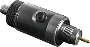
VIAVI I-Stop Reverse Test Probe for HFC Ingress Troubleshooting
Reverse test probe for KS tap ports that enables bi-directional HFC measurements and tracking of reverse ingress to the nearest tap.
- TAP input to output
- < 1.5 dB @5 to 50 MHz
- TAP input to output
- < 3.5 dB @ 50 MHz to 1.2 GHz
- TAP input to output (flatness)
- <1.5 dB in any 150 MHz Span
- TAP input to output with button depressed
- ≥ 4.5 dB, ≤ 8 dB @ 5 to 30 MHz
Overview
The VIAVI I-Stop is a reverse test probe used as a test accessory with most signal level meters, VIAVI DSP meters, VIAVI ONX meters, the VIAVI 860 DSPi, VIAVI PathTrak/XPERTrak and ViewPoint/SST.
The probe screws into the unused KS port of a distribution tap, where a spring-loaded stinger connects a nominal 20 dB resistive test point circuit to the seizure screw. The connection is bi-directional, so a signal level meter or analyzer connected to the probe can measure forward and reverse signals as well as reverse ingress. A built-in AC/DC blocking circuit protects the connected instrument from online power up to 100 volts.
Locating ingress
With the field meter connected to the test port, the technician presses the button on the side of the probe. If the headend ingress display decreases by 4 to 6 dB when the button is pressed, the ingress source is farther from the node than the test point; ingress that does not decrease enters the system nearer to the node. The probe has little or no visible effect on forward path signals.
The I-Stop contains a patented circuit used with the VIAVI PathTrak/XPERTrak or Guardian II return path maintenance systems to track reverse ingress sources down to the nearest tap, without removing reverse pads or diplexers and without disrupting forward or reverse service.
Key Features
- Taps unused KS ports for bi-directional measurements
- Compatible with SLMs, reverse and forward path analyzers
- Enables tracking reverse ingress to the nearest tap
- Protects instruments from line power damage (up to 100 volts)
- Spring-loaded stinger connects a nominal 20 dB resistive test point circuit
- Patented circuit for use with PathTrak/XPERTrak and Guardian II return path systems
- Little or no visible effect on forward path signals
Specifications
| TAP input to output |
< 1.5 dB @5 to 50 MHz
Specifications vary slightly based on manufacturer of the tap that is under test
|
|---|---|
| TAP input to output |
< 3.5 dB @ 50 MHz to 1.2 GHz
Specifications vary slightly based on manufacturer of the tap that is under test
|
| TAP input to output (flatness) |
<1.5 dB in any 150 MHz Span
Specifications vary slightly based on manufacturer of the tap that is under test
|
| TAP input to output with button depressed |
≥ 4.5 dB, ≤ 8 dB @ 5 to 30 MHz
Specifications vary slightly based on manufacturer of the tap that is under test
|
| TAP input to output with button depressed (forward band) |
≤ 1.0 dB Increase in Insertion Loss @ 54 MHz to 1.2 GHz
Specifications vary slightly based on manufacturer of the tap that is under test
|
| TAP input to I-Stop output |
20 ± 2.0 dB @ 5 MHz to 1.0 GHz
Specifications vary slightly based on manufacturer of the tap that is under test
|
|---|---|
| TAP input to I-Stop output |
20 +/-4 dB @ > 1GHz
Specifications vary slightly based on manufacturer of the tap that is under test
|
| Test point circuit |
nominal 20 dB resistive
Connected to the tap seizure screw via spring-loaded stinger
|
|---|---|
| Line power protection (AC/DC blocking) | up to 100 volts |
| Tap connection |
KS port
Unused KS port of a distribution tap
|
| Headend ingress decrease with button pressed |
4 to 6 dB
Indicates ingress source is farther from the node than the test point
|
Specifications are taken from the manufacturer's documentation. See the datasheet for complete and current values.
Applications
- Reverse path ingress troubleshooting
- Locating ingress sources down to the nearest tap
- Forward and reverse signal measurements at distribution taps
- Return path maintenance with PathTrak/XPERTrak
- Cable/HFC network field maintenance
Documents & Resources
Related Products
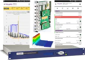
Return path monitoring system for HFC networks with live spectrum and QAM analysis, alarming and trending, supported by XPERTrak software.
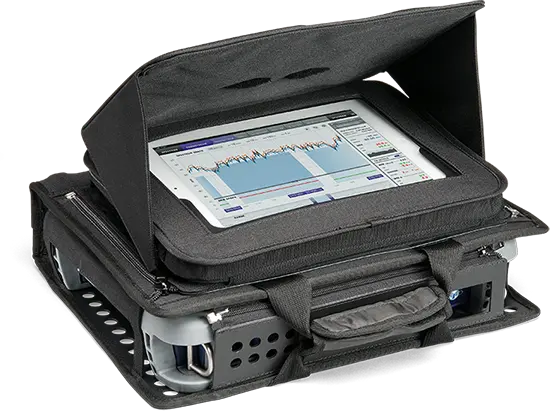
Digital spectrum and video analyzer with upstream noise troubleshooting for CCAP and Remote PHY cable networks, measuring 0.5 to 1,800 MHz.
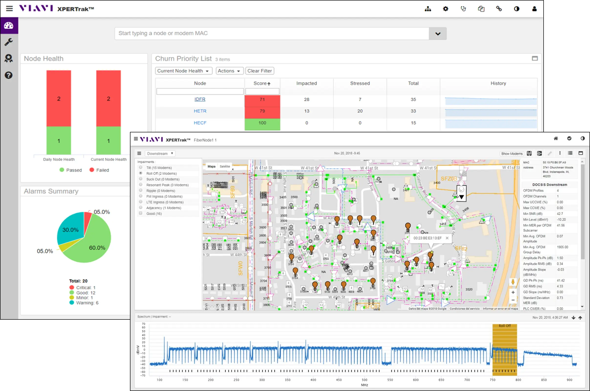
Service assurance and network maintenance system for HFC cable networks that ranks plant issues by subscriber QoE impact and churn risk.