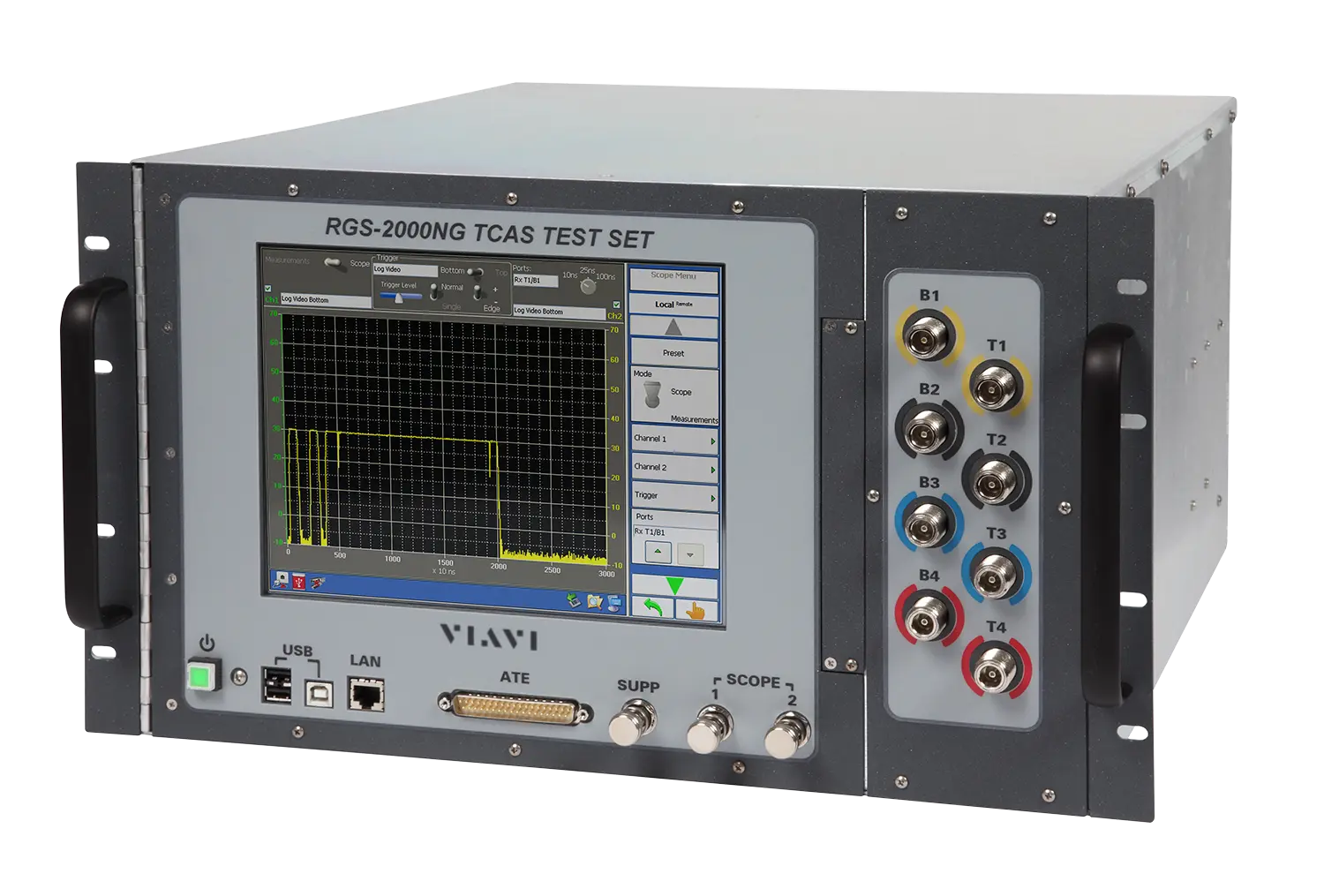
VIAVI RGS-2000NG NextGen TCAS Test Set and ADS-B Target Generator
RF signal generator/receiver for TCAS testing with ADS-B target generation and an optional transponder test capability.
- Range
- 952 MHz to 1223 MHz
- Resolution
- 100 KHz
- Accuracy
- ±10 KHz
Overview
The VIAVI RGS-2000NG is an RF signal generator/receiver for testing TCAS (Traffic Alert and Collision Avoidance System) equipment. An option adds testing of transponder LRUs. The instrument replaces the earlier RGS-2000 and is intended for engineering development, design validation, manufacturing and return-to-service testing.
The RGS-2000NG uses software-driven digital modulation, so new features, capabilities or changes required by industry updates can be added in the field through software updates. It also works as a TCAS and ADS-B target generator. In scenario mode it simulates dynamic and static targets at 1090 MHz, and with the appropriate options it simulates UAT targets at 978 MHz and blocks of Ground Station and TCAS messages at 1030 MHz.
Operators control the test set from a 10.4 inch touch screen LCD, or remotely over GPIB or Ethernet. Other capabilities include four-port antenna simulation, ADS-B squitter encode/decode, pulse and frequency measurement, hybrid surveillance and data parsing for analysis. The test set can perform most MOPS tests for DO-185A, DO-185B, DO-260, DO-260A, DO-260B, DO-260C, DO-282B, DO-282C, DO-181E and DO-300.
Key Features
- Software-driven design allows field updates for new features, capability or modifications due to industry changes
- TCAS and ADS-B target generator
- Simulates 32 dynamic and 568 static ADS-B/TCAS targets at 1090 MHz in scenario mode
- Simulates 32 dynamic and 1,500 static UAT targets at 978 MHz as airborne or ground link messages (requires RGSNGOPT10 Transponder, RGSNGOPT14 Multi-receiver, or RGSNGOPT13 UAT options)
- Simulates blocks of up to 1,000 messages for Ground Station and TCAS messages at 1030 MHz (requires RGSNGOPT14 Multi-receiver)
- ADS-B squitter encode/decode
- Pulse and frequency measurement
- Transponder test option for Modes A, C, S
- 10.4 inch touch screen LCD display for operator control of all test set capabilities
- Remote control via GPIB or Ethernet
- Four port antenna simulation
- Hybrid surveillance
- Data parsing for analysis
Specifications
| Range | 952 MHz to 1223 MHz |
|---|---|
| Resolution | 100 KHz |
| Accuracy | ±10 KHz |
| Range (TCAS) | -20 to -90 dBm (Low Power Mode); +1 to -69 dBm (High Power Mode) |
|---|---|
|
Range (Transponder)
RGSNGOPT10
|
-20 to -90 dBm |
|
Range (UAT)
RGSNGOPT13
|
+1 to -98 dBm
T1 port only
|
|
Range (Multi-Receiver)
RGSNGOPT14
|
+1 to -69 dBm (High Power Mode); -20 to -90 dBm (Low Power Mode) |
| Resolution | 1 dB |
| Accuracy |
±1 dB
1030 and 1090 MHz (978 MHz with UAT or Multi-Receiver options installed)
|
| Harmonics | <-50 dBc |
|---|---|
| Spurious |
<-55 dBc
350 to 1800 MHz
|
| Residual FM | 250 Hz Peak |
| Phase Noise | <-80 dBc/Hz @ 100 KHz |
| Power range |
±20 dB
Absolute output power under any test condition is limited to the ranges shown under Power
|
|---|---|
| Power resolution | 0.1 dB |
| Power accuracy | ±1 dB |
| Timing range | ±1 µs |
| Timing resolution | ±25 ns |
| Timing accuracy | ±10 ns |
| Pulse On/Off Ratio |
>80 dB
1030 and 1090 MHz (978 MHz with UAT or Multi-Receiver options installed)
|
|---|---|
| ATCRBS Replies (TCAS) pulse position, nominal (all pulses) |
1.45 µs from previous pulse
Pulse timing accuracy applies with transmitters configured for 50/50 ns rise/fall time mode only
|
| Pulse position resolution | 25 ns |
| Pulse position accuracy | ±10 ns |
| Pulse width resolution |
25 ns
Specified accuracies apply to pulses of width ≥ 0.2 µs
|
| Pulse rise/fall time, TCAS Low Power Mode (available settings) | <50/<50 ns, 75/110 ns, 100/200 ns, 230/230 ns, 600/600 ns |
| Pulse rise/fall time, TCAS High Power Mode | <50/<50 ns |
| Pulse rise/fall time accuracy | ±25 ns |
|
Pulse rise/fall time, Transponder Test Mode
RGSNGOPT10
|
<50/<50 ns, fixed |
|
Pulse amplitude, Transponder Test Mode (relative to P1)
RGSNGOPT10
|
+9 to -19 dB
ATCRBS (all pulses) and Mode S Interrogation (P2, P5 and P6); resolution 1 dB, accuracy ±1 dB
|
| Range |
0 to 359°
Phase and magnitude directional
|
|---|---|
| Resolution | 1° |
| Accuracy, Low Power Mode, 4-Port Antenna (phase directional) |
4-Port Formula, ±2°
Standard deviation <1° at any simulated bearing; ±4° deviation between any port referenced to port 1. 30 minute wait required after changing power mode
|
| Accuracy, Low Power Mode, 2-Port Antenna (phase directional) | Port to Port, ±4° |
| Accuracy, Low Power Mode (magnitude directional) | 4-Port Formula, ±2°; Power Table, ±0.556 dB (equivalent to ±2°) |
| Accuracy, High Power Mode |
4-Port Formula, ±5° typical
Phase and magnitude directional
|
| Range simulation, Mode S | 0 to 160 nmi |
|---|---|
| Range simulation, Mode C | 0.5 to 160 nmi |
| Range simulation resolution | .001 nmi |
| Range simulation accuracy | ±200 ft |
| Velocity range |
2000 kts
Resolution 1 kt, accuracy ±1 kt
|
| Vertical speed range |
±32,608 ft/min
Resolution 64 ft/min, accuracy ±64 ft/min
|
| Altitude simulation range |
-1000 to +126700 ft
Accuracy ±25 ft
|
| Altitude simulation resolution | < 50175 ft altitude, 25 or 100 ft; >50175 ft altitude, 100 ft |
|
Interrogation table/burst mode, # of messages
RGSNGOPT10
|
1 to 1000 messages |
|---|---|
|
Interrogations/Burst
RGSNGOPT10
|
1 to 10 K |
| Block transmissions, number of messages (TCAS) | 1 to 1000 |
|
Block transmissions, number of messages (Transponder)
RGSNGOPT10
|
1 to 2000 |
| Number of blocks | 1 to 50,000 or infinite |
| Block period range |
10 ms to 90 seconds
Resolution 1 ms, accuracy ±1 ms
|
|
PRF, single interrogations
RGSNGOPT10
|
1 to 10 KHz
Resolution 1 Hz, accuracy 0.1% of setting
|
|
Interlace ratio
RGSNGOPT10
|
1:1 to 1:1000 |
| Decoding, ATCRBS | Interrogations (TCAS) and Replies (Transponder) |
|---|---|
| Decoding, Mode S | Interrogations (TCAS) and Replies (Transponder) |
|
Decoding, UAT
RGSNGOPT13
|
Ground and Airborne Messages
B1 port only
|
| Range, 1030/1090 MHz (TCAS/Transponder) | +17 to +60 dBm |
|
Range, 978 UAT
RGSNGOPT13
|
+30 to +57 dBm |
| Power (1030 and 1090 MHz) range |
+17 to +60 dBm
Resolution 0.1 dB, accuracy ±0.5 dB
|
|---|---|
| Frequency, pulse measurement type |
1030 MHz (±3 MHz); 1090 MHz (±3 MHz)
Resolution 1 KHz, accuracy ±50 KHz
|
| Frequency, 1030 measurement type |
1030 MHz ±50 KHz
TCAS, DO-185, Mode S, Test-Mode 3 only; resolution 100 Hz, accuracy ±1 KHz
|
| Phase (TCAS) |
0 to 359°; any port reference to T1/B1
Resolution 1 degree, accuracy ±4 degree
|
| Pulse spacing accuracy |
±10 ns
Resolution 1 ns; applies for input signals ≥ +33 dBm
|
| Pulse width accuracy |
±15 ns
Resolution 1 ns; applies for input signals ≥ +33 dBm
|
|
Reply delay (Transponder) accuracy
RGSNGOPT10
|
±50 ns
Resolution 25 ns
|
|
Percent reply (Transponder) range
RGSNGOPT10
|
0 to 100 %
Sample size equal to PRF or 200, whichever is greater; resolution 0.1 %, accuracy ±1%
|
|
Mode S squitter (Transponder) accuracy
RGSNGOPT10
|
±1 ms, ±2.5 ppm
Resolution 1 ms
|
| VSWR | <1.4 (978, 1030 and 1090 MHz) |
|---|---|
| Cross coupling, adjacent ports | -17 to -20 dB |
| Insertion loss, SA AMP |
-31 ±5 dB
Antenna ports to spectrum analyzer outputs; Mod Strike 4 required
|
|---|---|
| Insertion loss, SA Thru |
-59.5 ±5 dB
Mod Strike 4 required
|
| Display | 10.4 inch touch screen LCD |
|---|---|
| Remote control | GPIB or Ethernet |
| Voltage range | 100 to 240 VAC, 50 to 60 Hz |
|---|---|
| Power consumption | 150 W typical |
| Temperature, full specified performance |
23° ±5° C (73.4°F ±5°)
Requires 1 hour warm-up period to meet specified performance
|
|---|---|
| Operating temperature | 0° to +40°C (32° to +104°F) |
| Storage temperature | 0° to +71°C (32° to +159.8°F) |
| Relative humidity | 0 to 95% non-condensing |
| Size (test set only) |
10.5” H x 19” W x 24” D (26.67 cm x 48.26 cm x 60.9 cm)
Web page lists 26.7 cm x 48.3 cm x 60.9 cm
|
|---|---|
| Weight | 43 lbs. (19.5 kg) |
| Standards | CE, UL/EN 61010-1, EN 61326-1, MIL-PRF-28800F (Class 3 Device) |
|---|
Specifications are taken from the manufacturer's documentation. See the datasheet for complete and current values.
Applications
- Engineering development
- Certification
- Manufacturing
- Service and return-to-service testing
- MOPS testing for DO-185A, DO-185B, DO-260, DO-260A, DO-260B, DO-260C, DO-282B, DO-282C, DO-181E and DO-300
- Replacement for the RGS-2000
- TCAS computers
- ADS-B In receivers
- ADS-B In ground station receivers
- ADS-R, TIS-B ground station transmitters
- Transponders Mode S/ADS-B Out (transponder option)
Options & Accessories
| Option | Description |
|---|---|
| RGSNGOPT10 | Transponder — Transponder test option for Modes A, C, S |
| RGSNGOPT13 | UAT 978MHz — UAT target simulation and decoding at 978 MHz |
| RGSNGOPT14 | Multi-Receiver — Required for simulating blocks of up to 1,000 Ground Station and TCAS messages at 1030 MHz |
| Option 15 | DO-260B MOPS Test |