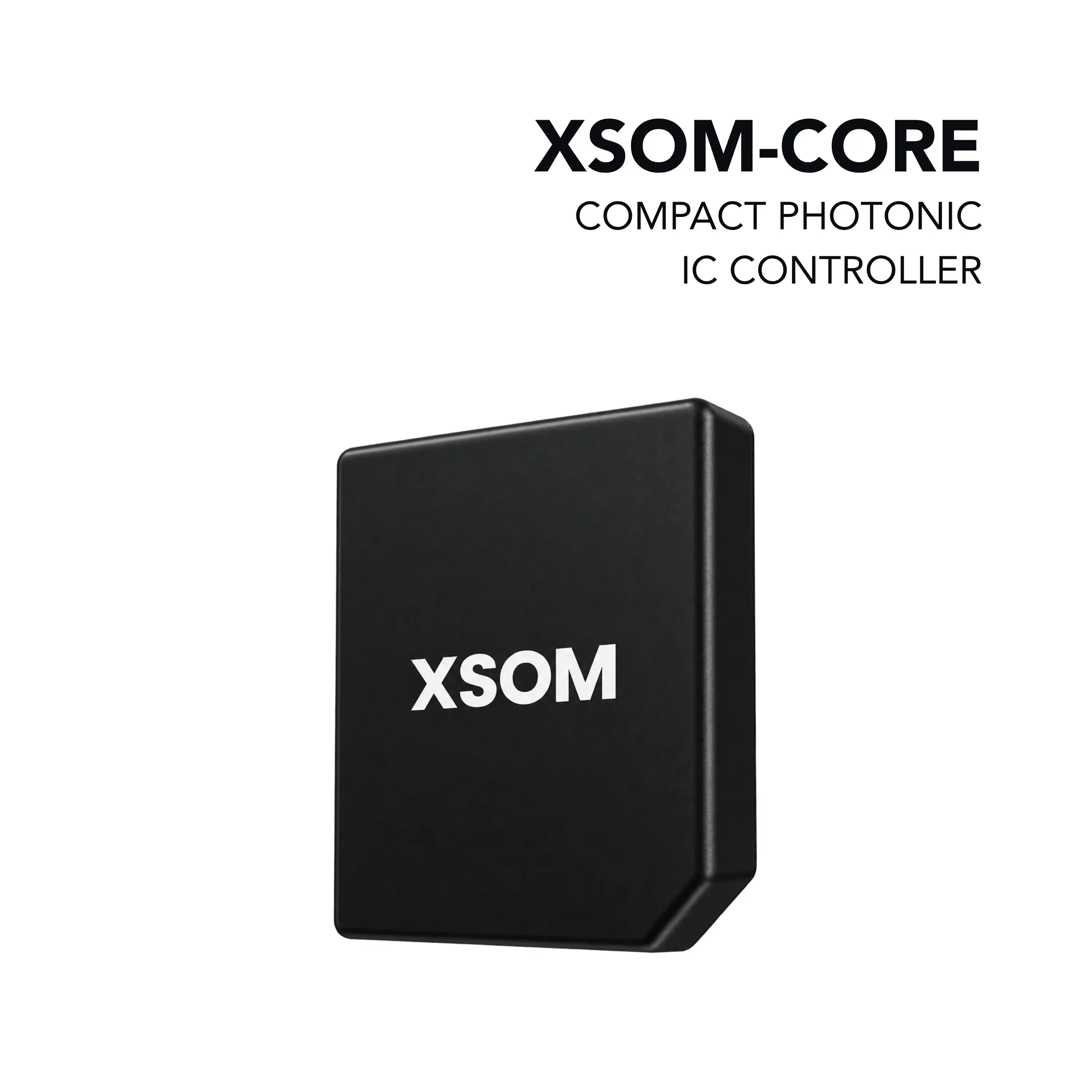
Nicslab XSOM-CORE System-on-Module for Driving Photonic Integrated Circuits
System-on-Module with 16 voltage outputs, 16 current-limited outputs and 32 analog inputs for precision control and measurement of PICs.
- Output voltage range
- 0–5 V, 0–10 V, 0–20 V (unipolar); ±5 V, ±10 V, ±20 V (bipolar)
- DAC resolution
- 16 bits
- Update rate
- 100 kHz
- Output voltage settling time (5 V span)
- 10 µs
Overview
XSOM-CORE is a System-on-Module (SoM) for precision control and measurement of Photonic Integrated Circuits (PICs). All signal and power connections are brought out on a single 262-pin SO-DIMM connector, which mates with a carrier board that supplies power and routes signals to the device under test (DUT).
The module provides 16 voltage output channels with selectable bipolar (±5 V, ±10 V, ±20 V) or unipolar (0–5 V, 0–10 V, 0–20 V) ranges, driven by a 16-bit DAC with update rates up to 100 kHz per channel. Sixteen programmable current-limited output channels support current limits up to 300 mA per channel, also at 16-bit resolution and 100 kHz update rate.
For signal acquisition, XSOM-CORE includes 16 single-ended analog inputs (0–10 V) and 16 differential analog inputs (±0.1 V differential, 0–10 V common-mode), each with 16-bit ADC resolution and sampling rates up to 100 kHz. Host communication uses a standard Ethernet interface.
Carrier board integration
XSOM-CORE is used together with a carrier board that forms the basis of a complete system. The carrier board powers the module and can act as a passive interface routing signals to the DUT, as an active expansion platform adding peripherals, connectivity or I/O, or both. The module is intended for industrial, laboratory, and test-and-measurement applications.
Key Features
- 262-pin SO-DIMM connector for all signals and power
- 16 voltage output channels, up to ±20 V (bipolar) or 0–20 V (unipolar)
- 16 current-limited output channels, programmable up to 300 mA per channel
- 16 single-ended analog input channels
- 16 differential analog input channels
- Ethernet interface for host communication
- 16-bit DAC and ADC resolution
- Update (output) or sampling (input) rate up to 100 kHz per channel
- Bipolar or unipolar supply operation
Specifications
| Output voltage range |
0–5 V, 0–10 V, 0–20 V (unipolar); ±5 V, ±10 V, ±20 V (bipolar)
Selectable, per channel; VDD ≥ VMAX + 1.5, VSS ≤ VMIN - 1.5
|
|---|---|
| DAC resolution | 16 bits |
| Update rate |
100 kHz
Max
|
| Output voltage settling time (5 V span) | 10 µs |
| Output voltage settling time (10 V span) | 10 µs |
| Output voltage settling time (20 V span) | 15 µs |
| Output voltage settling time (40 V span) | 25 µs |
| Output current | -10 to 10 mA |
| Slew rate (0-5 V range) |
0.8 V/µs
10%FSR to 90%FSR
|
| Slew rate (all other ranges except 40 V span) |
4 V/µs
10%FSR to 90%FSR
|
| Output impedance (DAC code at midscale) |
0.05 Ω
DAC unloaded
|
| Output impedance (DAC code at full scale) |
0.05 Ω
DAC unloaded
|
| Output impedance (DAC code at negative full scale) |
25 Ω
DAC unloaded
|
| Current limit range | 0 to 300 mA |
|---|---|
| Resolution | 16 bits |
| Update rate |
100 kHz
Max
|
| PCLIx operating range | 0 to PCLV+ V |
| Voltage input range | 0 to 10 V |
|---|---|
| Resolution | 16 bits |
| Sampling rate |
100 kHz
Max
|
| Differential input range | -0.1 to 0.1 V |
|---|---|
| Common-mode range | 0 to 10 V |
| Resolution | 16 bits |
| Sampling rate |
100 kHz
Max
|
| VDD input voltage |
15 to 21.5 V
Relative to GND
|
|---|---|
| VSS input voltage |
-21.5 to 0 V
Relative to GND
|
| Maximum supply span |
15 to 43 V
Voltage Span = VDD - VSS
|
| 5V operating voltage |
4.5 to 5.5 V
Relative to GND
|
| PCLV+ input voltage |
3.3 to VDD V
Relative to GND
|
| PCLV- input voltage |
-3.3 to 0 V
Relative to GND
|
| Carrier board connector |
262-pin SO-DIMM
All signal and power connections
|
|---|---|
| Host interface | Ethernet (MDI pairs 0–3) |
Applications
- Photonic integrated circuit control and measurement
- Industrial applications
- Laboratory applications
- Test and measurement applications
- Custom carrier board system integration