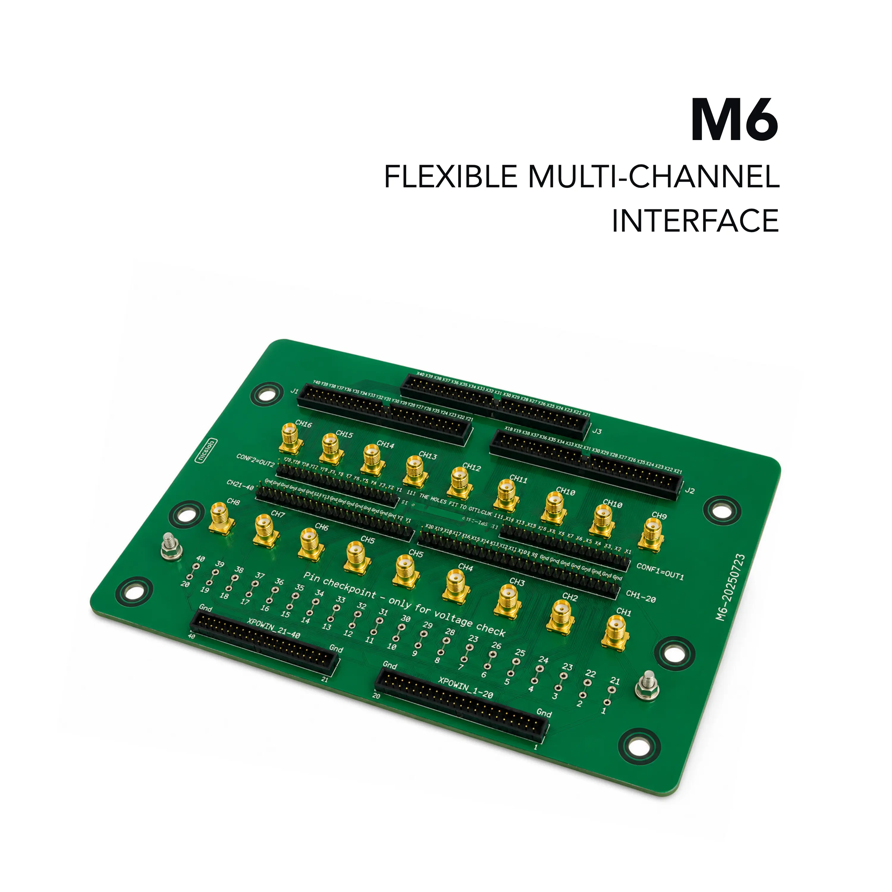
Multiconnector M6 40-Channel Multi-Connector Board with IDC, SMA and 2.54 mm Pin-Header Interfaces
A 40-channel passive multi-connector board for XPOW/XDAC outputs with IDC, SMA and 2.54 mm pin-header interfaces.
- Dimensions (L × W × H)
- 12 × 16 × 1.2 cm
- Channels
- 40
- Board type
- Passive interconnect / reconfiguration PCB
Overview
The Nicslab Multiconnector M6 is a 40-channel multi-connector board that takes the 40 channel outputs of an XPOW or XDAC system and makes them available through several connector types. It has 2.54 mm pin outputs, SMA outputs and IDC connectors.
The same 40 channels can be reached through the IDC, SMA or pin-header connectors at the same time. This makes the board suitable for setups where several devices under test use different connection types. CONF reconfiguration pins let users remap channel and GND assignments, and per-channel and GND checkpoints allow verification with a multimeter.
Wiring
The IDC connectors carrying the Y and X channel groups (points B and C) share channel pins with the CONF headers at points D and E and with IDC connector A. Points J and K connect to the main system and come pre-wired from the factory, with GND and the channel outputs already mapped. Points F and G correspond directly to J and K: the top row is GND and the bottom row (C1–C40) carries the channel outputs. The SMA connectors at point H are wired straight to the main system through J and K, so they need no extra reconfiguration.
Usage
A DUT with SMA inputs connects directly to any available SMA connector (CH1–CH16), and the matching channel is then selected in the control GUI. A DUT with an IDC input connects to point A, B or C with an IDC cable, and the matching channel is selected in the GUI.
Key Features
- 40 channels broken out across three IDC connectors (points A–C), 2.54 mm CONF pin headers (points D/E) and SMA connectors (point H, 16 Ch)
- Dedicated CONF reconfiguration pin headers (points D and E) to remap channel/GND assignments
- Ground checkpoints (2 pins, points L/M) for multimeter verification
- Per-channel output checkpoints (point I, 1–40) for verification without disconnecting cabling
- Direct pass-through connectors (points J/K) to the main system, factory pre-wired
- Compact, passive PCB with no external power required beyond what passes through from the main system
- Supports multiple simultaneous DUT connection types (IDC, SMA and/or pin header) from a single board
Specifications
| Dimensions (L × W × H) | 12 × 16 × 1.2 cm |
|---|---|
| Channels | 40 |
| Board type | Passive interconnect / reconfiguration PCB |
| A | IDC Connector 1 50 pins (X1, X20-X40, Y1, Y20-Y35) |
|---|---|
| B | IDC Connector 2 40 pins (Y1-Y40) |
| C | IDC Connector 3 40 pins (X1-X40) |
| D | CONF 2x20-2 pin header 2.54 mm (Y1 – Y40) |
| E | CONF 2x20-2 pin header 2.54 mm (X1 – X40) |
| F | 2x20-5 pin header 2.54 mm ((C21 – C40) + GND) |
| G | 2x20-5 pin header 2.54 mm ((C1 – C20) + GND) |
| H | SMA Connector (16 Ch) |
| I | Channel 1-40 output check point pin (1 - 40) |
| J | 21 – 40 CH in pin header 2.54 mm (21 – 40) |
| K | 1 – 20 CH in pin header 2.54 mm (1 – 20) |
| L | GND check point 1 pin (41) |
| M | GND check point 2 pin (42) |
| Output connector | IDC (points A–C), 2.54 mm pin header (points D/E), or SMA (point H) — multiple types available simultaneously |
|---|---|
| Reconfiguration | CONF headers (points D/E) allow remapping of channel/GND assignment away from factory default |
| Verification | GND checkpoints (L/M) and per-channel checkpoints (I, 1–40) for multimeter probing |
Applications
- XPOW/XDAC channel output breakout
- Connecting multiple DUTs with different connector types
- Channel verification with a multimeter