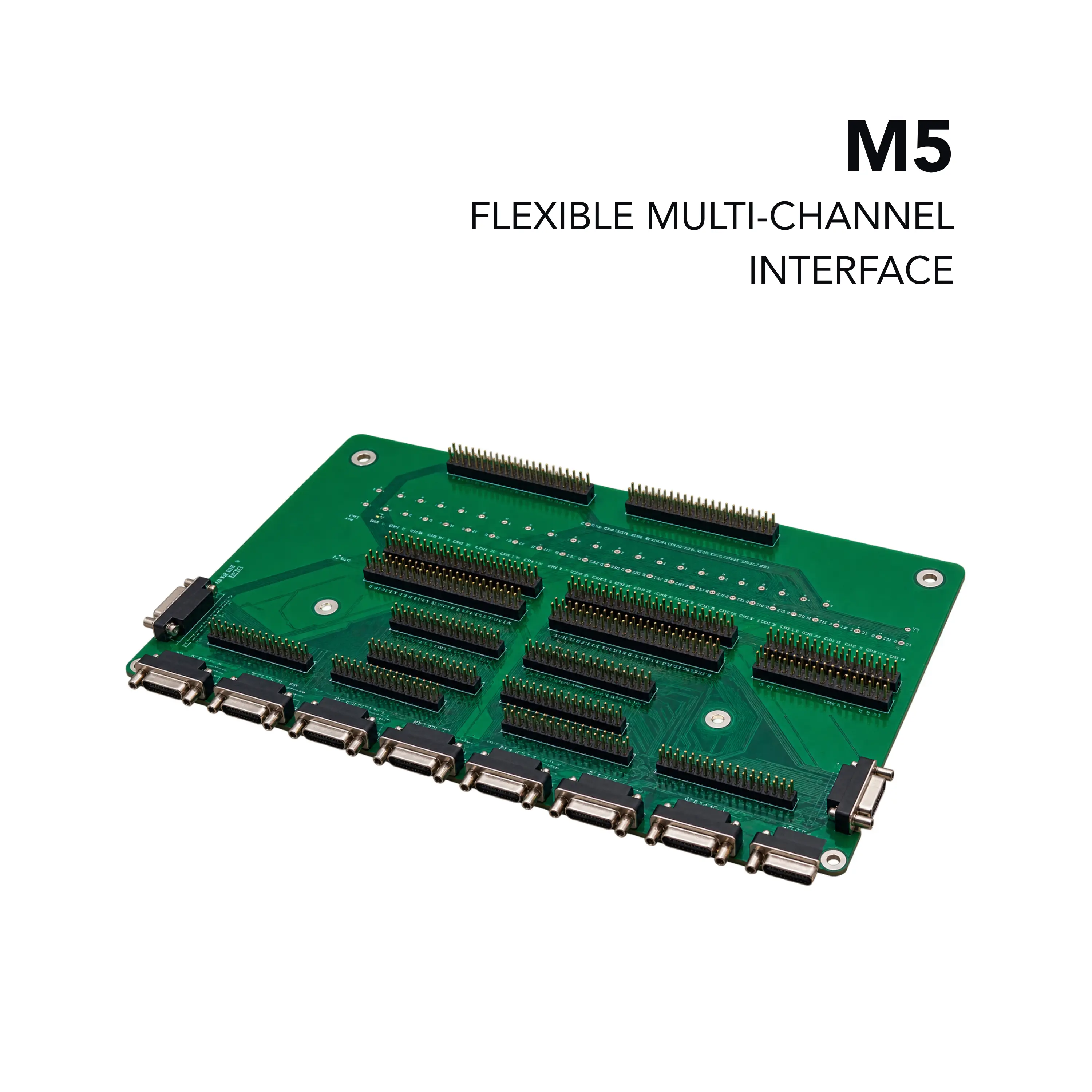
Nicslab Multiconnector M5 120-Channel D-Sub25 and Pin-Header Breakout Board
A 120-channel passive multi-connector board with D-Sub25 and 2.54 mm pin-header interfaces, a CONF remapping header and a channel checkpoint row.
- Dimensions (L × W × H)
- 20 × 30 × 1.2 cm
- Channels
- 120
- Board type
- Passive interconnect / reconfiguration PCB
Overview
The Nicslab Multiconnector M5 is a 120-channel multi-connector board with D-Sub and 2.54 mm pin-header interfaces. It is designed to accommodate the 120 channels output from an Xpow-120AX box, 4 × 40AX, or XDAC, and offers the same flexibility as the other boards in the multi-connector family.
The same 120 channels can be accessed either through the board's D-Sub25 connectors or through 2.54 mm pin headers. Point A breaks the channels out across ten D-Sub25 connectors with 12 channels each, while points B and C carry the X1–X120 and Y1–Y120 channel pins in pin-header form.
Configuration and verification
Point C adds a CONF 6x20 pin header (C1–C120) that allows the channel and GND assignment to be remapped away from the factory default using jumper wire. A channel output checkpoint row at point D (1–120) allows multimeter verification without disconnecting cabling.
Connection to the main system
Points E, F and G connect to the main system and are pre-wired at the factory, each carrying one third of the 120 channels (81–120, 41–80 and 1–40 respectively). The board is a passive PCB and requires no external power beyond what passes through from the main system.
Key Features
- 120 channels broken out across ten D-Sub25 connectors (point A, 12 channels each)
- 6×40 pin header 2.54 mm (point B) carrying the full X1–X120 and Y1–Y120 channel set
- 6×40 pin header 2.54 mm with a 6×20 CONF pin header (point C) for channel remapping (C1–C120)
- Channel output checkpoint row (point D, 1–120) for multimeter verification without disconnecting cabling
- Factory pre-wired pass-through connectors to the main system (points E, F and G), split by channel range 81–120, 41–80 and 1–40
- Compact, passive PCB with no external power required beyond what passes through from the main system
- Supports D-Sub25 and pin-header DUT connections simultaneously from a single board
Specifications
| Dimensions (L × W × H) | 20 × 30 × 1.2 cm |
|---|---|
| Channels | 120 |
| Board type | Passive interconnect / reconfiguration PCB |
| A | 10x12 ch D-Sub 25 connector |
|---|---|
| B | 6x40 pin header 2.54 mm (X1 – X120, Y1 – Y120) |
| C | 6x40 pin header 2.54 mm (X1 – X120, Y1 – Y120) & CONF 6x20 pin header 2.54 mm (C1 – C120) |
| D | Channel output check point 120 pin (1 - 120) |
| E | 81 – 120 CH in pin header 2.54 mm (81 – 120) |
| F | 41 – 80 CH in pin header 2.54 mm (41 – 80) |
| G | 1 – 40 CH in pin header 2.54 mm (1 – 40) |
| Output connector | D-Sub25 (point A) or 2.54 mm pin header (points B/C) — both available simultaneously |
|---|---|
| Reconfiguration | CONF 6x20 pin header at point C allows remapping of channel assignment away from factory default |
| Verification | Channel output checkpoint (point D, 1–120) for multimeter probing |
Applications
- Breakout of 120-channel outputs from Xpow-120AX, 4 × 40AX or XDAC systems
- Connecting DUTs with D-Sub25 inputs
- Connecting DUTs with 2.54 mm pin-header inputs
- Channel remapping via jumper wire
- Multimeter verification of channel outputs