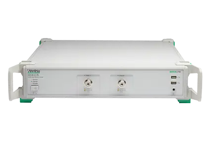
ShockLine MS46322B Economy 2-Port Vector Network Analyzer, 1 MHz to 8/20/43.5 GHz
Compact 2U, 2-port economy vector network analyzer covering 1 MHz to 8, 20 or 43.5 GHz with greater than 100 dB dynamic range.
- Operating frequency
- 1 MHz to 8 GHz
- Operating frequency
- 1 MHz to 20 GHz
- Operating frequency
- 1 MHz to 43.5 GHz
- Frequency resolution
- 1 Hz
Overview
The Anritsu ShockLine MS46322B is a series of 2-port economy vector network analyzers (VNAs) offered in three frequency ranges: 1 MHz to 8 GHz, 1 MHz to 20 GHz and 1 MHz to 43.5 GHz. The instrument performs S-parameter and time domain measurements and is intended for testing RF and microwave passive devices, including millimeter-wave antennas and passive 5G components, in engineering, manufacturing and education settings.
The MS46322B is based on Anritsu's patented ShockLine VNA-on-chip technology, which simplifies the internal VNA architecture at high frequencies, reduces instrument cost and improves accuracy and measurement repeatability.
All models are housed in a self-contained 2U chassis that includes the power supply and computer. One frequency option is selected at order time; it determines the test port connector type (N(f), ruggedized K(m) or ruggedized Extended-K(m)).
Remote control and user interface
The analyzer is controlled remotely over LAN using SCPI commands, with software drivers available for common programming environments, which suits integration into rack-mount test systems. For manual operation, a full graphical user interface is available when a user-supplied touchscreen monitor, keyboard and mouse are connected. The GUI and SCPI interface are common across the ShockLine family. A removable solid state drive is standard, supporting secure and compartmentalized use.
Key Features
- Guaranteed performance to 43.5 GHz with Extended K ports
- Suited to testing RF and microwave devices, mmWave antennas and other passive 5G components
- Fast sweep speed and wide dynamic range to reduce test times
- Corrected directivity that reduces measurement uncertainty
- Optional time domain with time gating for fault identification
- Industry-standard LAN interface for remote control
- Standard removable hard drive for security-sensitive users
- Common GUI and SCPI interface within the ShockLine family
- USB ports for connecting a user-provided monitor, keyboard and mouse
- Compact 2U package for efficient use of rack space
- Optional Universal Fixture Extraction (UFX) software for test fixture de-embedding
- Compatible with the 36585K AutoCal unit for calibrations up to 40 GHz
Specifications
|
Operating frequency
MS46322B-010
|
1 MHz to 8 GHz |
|---|---|
|
Operating frequency
MS46322B-020
|
1 MHz to 20 GHz |
|
Operating frequency
MS46322B-043
|
1 MHz to 43.5 GHz |
| Frequency resolution | 1 Hz |
| Frequency accuracy |
± 1.0 ppm
At time of calibration
|
| Frequency stability |
± 1.0 ppm from -10 °C to +55 °C
Typical
|
| Aging |
± 1.0 ppm/yr
Typical
|
| 1 MHz to 10 MHz |
85 dB (105 dB typical)
High source power minus RMS noise floor, 10 Hz IF bandwidth, isolation calibration
|
|---|---|
| > 10 MHz to 8 GHz |
100 dB (115 dB typical)
Crosstalk may reduce dynamic range up to 20 dB (typical) at IF bandwidths ≤ 10 kHz when measuring highly reflective DUTs from 4 GHz to 8 GHz; reflection measurements not affected
|
| > 8 GHz to 40 GHz |
100 dB (110 dB typical)
Decrease specification by 5 dB between 8 GHz and 14 GHz
|
|
> 40 GHz to 43.5 GHz
MS46322B-043
|
97 dB (110 dB typical) |
| Receiver compression level, 1 MHz to 43.5 GHz |
+5 dBm
Port power beyond which response may be compressed more than 0.1 dB; characteristic
|
|---|---|
| High level noise, 1 MHz to < 20 MHz |
0.03 dB (0.005, typical); < 0.2 deg (< 0.035 typical)
100 Hz IF bandwidth, High power level, RMS; characteristic
|
| High level noise, 20 MHz to 20 GHz |
0.006 dB (0.001, typical); < 0.1 deg (< 0.05 typical)
100 Hz IF bandwidth, High power level, RMS; characteristic
|
| High level noise, > 20 GHz to 40 GHz |
0.006 dB (0.001, typical); < 0.15 deg (< 0.05 typical)
100 Hz IF bandwidth, High power level, RMS; characteristic
|
|
High level noise, > 40 GHz to 43.5 GHz
MS46322B-043
|
0.009 dB (0.001, typical); < 0.18 deg (< 0.05 typical)
100 Hz IF bandwidth, High power level, RMS; characteristic
|
| Output power, High (default), 1 MHz to 8 GHz |
5 dBm
Typical
|
| Output power, High (default), > 8 GHz to 43.5 GHz |
–3 dBm
Typical
|
| Output power, Low, 1 MHz to 43.5 GHz |
–20 dBm
Typical
|
| Measurement stability, 10 MHz to 43.5 GHz |
0.02 dB/°C magnitude, 0.3 deg/°C phase
Ratio measurement with ports shorted; typical
|
| Directivity, 1 MHz to 43.5 GHz |
> 8 dB
User and system correction off; typical
|
|---|---|
| Port match, 1 MHz to 43.5 GHz |
> 8 dB
User and system correction off; typical
|
|
1 MHz to 6 GHz
MS46322B-010
|
Directivity ≥ 42 dB, Source Match ≥ 33 dB, Load Match ≥ 42 dB, Reflection Tracking ±0.15 dB, Transmission Tracking ±0.06 dB
12-term SOLT calibration; load match and tracking are characteristic
|
|---|---|
|
> 6 GHz to 8 GHz
MS46322B-010
|
Directivity ≥ 37 dB, Source Match ≥ 33 dB, Load Match ≥ 37 dB, Reflection Tracking ±0.15 dB, Transmission Tracking ±0.06 dB
12-term SOLT calibration; load match and tracking are characteristic
|
|
1 MHz to 10 GHz
MS46322B-020
|
Directivity ≥ 42 dB, Source Match ≥ 33 dB, Load Match ≥ 42 dB, Reflection Tracking ±0.15 dB, Transmission Tracking ±0.06 dB
12-term SOLT calibration; load match and tracking are characteristic
|
|---|---|
|
> 10 GHz to 20 GHz
MS46322B-020
|
Directivity ≥ 36 dB, Source Match ≥ 26 dB, Load Match ≥ 36 dB, Reflection Tracking ±0.15 dB, Transmission Tracking ±0.05 dB
12-term SOLT calibration; load match and tracking are characteristic
|
|
1 MHz to 10 GHz
MS46322B-043
|
Directivity ≥ 42 dB, Source Match ≥ 33 dB, Load Match ≥ 42 dB, Reflection Tracking ±0.15 dB, Transmission Tracking ±0.06 dB
12-term SOLT, TOSLK50A-43.5 or TOSLKF50A-43.5 with generic calibration coefficients
|
|---|---|
|
> 10 GHz to 20 GHz
MS46322B-043
|
Directivity ≥ 36 dB, Source Match ≥ 26 dB, Load Match ≥ 36 dB, Reflection Tracking ±0.15 dB, Transmission Tracking ±0.06 dB
Generic calibration coefficients
|
|
> 20 GHz to 30 GHz
MS46322B-043
|
Directivity ≥ 32 dB, Source Match ≥ 22 dB, Load Match ≥ 32 dB, Reflection Tracking ±0.15 dB, Transmission Tracking ±0.06 dB
Generic calibration coefficients
|
|
> 30 GHz to 40 GHz
MS46322B-043
|
Directivity ≥ 30 dB, Source Match ≥ 20 dB, Load Match ≥ 30 dB, Reflection Tracking ±0.15 dB, Transmission Tracking ±0.06 dB
Generic calibration coefficients
|
|
> 40 GHz to 43.5 GHz
MS46322B-043
|
Directivity ≥ 28 dB, Source Match ≥ 20 dB, Load Match ≥ 28 dB, Reflection Tracking ±0.20 dB, Transmission Tracking ±0.16 dB
Generic calibration coefficients
|
|
> 0.05 GHz to 10 GHz
MS46322B-043
|
Directivity ≥ 45 dB, Source Match ≥ 45 dB, Load Match ≥ 44 dB, Reflection Tracking ±0.15 dB, Transmission Tracking ±0.06 dB
12-term SOLT, TOSLK50A-43.5 or TOSLKF50A-43.5 with .s1p definitions
|
|---|---|
|
> 20 GHz to 30 GHz
MS46322B-043
|
Directivity ≥ 45 dB, Source Match ≥ 44 dB, Load Match ≥ 44 dB, Reflection Tracking ±0.15 dB, Transmission Tracking ±0.06 dB
.s1p definitions
|
|
> 30 GHz to 40 GHz
MS46322B-043
|
Directivity ≥ 45 dB, Source Match ≥ 42 dB, Load Match ≥ 44 dB, Reflection Tracking ±0.15 dB, Transmission Tracking ±0.06 dB
.s1p definitions
|
|
> 40 GHz to 43.5 GHz
MS46322B-043
|
Directivity ≥ 42 dB, Source Match ≥ 41 dB, Load Match ≥ 41 dB, Reflection Tracking ±0.2 dB, Transmission Tracking ±0.16 dB
.s1p definitions
|
|
1 MHz to < 10 GHz
MS46322B-043
|
Directivity ≥ 50 dB, Source Match ≥ 49 dB, Load Match ≥ 42 dB, Reflection Tracking ±0.15 dB, Transmission Tracking ±0.06 dB
12-term calibration with 36585K, type K connectors; typical
|
|---|---|
|
10 GHz to < 20 GHz
MS46322B-043
|
Directivity ≥ 45 dB, Source Match ≥ 49 dB, Load Match ≥ 36 dB, Reflection Tracking ±0.15 dB, Transmission Tracking ±0.05 dB
Typical
|
|
20 GHz to < 30 GHz
MS46322B-043
|
Directivity ≥ 45 dB, Source Match ≥ 45 dB, Load Match ≥ 36 dB, Reflection Tracking ±0.10 dB, Transmission Tracking ±0.05 dB
Typical
|
|
30 GHz to 40 GHz
MS46322B-043
|
Directivity ≥ 45 dB, Source Match ≥ 45 dB, Load Match ≥ 30 dB, Reflection Tracking ±0.10 dB, Transmission Tracking ±0.05 dB
Typical
|
| Measurement speed |
140 µs/point, typical
Per-point single sweep time incl. data to memory; 300 kHz IFBW, 1601 points, 2-port calibrated. Web page and fact sheet state 130 µs/point
|
|---|---|
| Data transfer time, SCPI over LAN, ASCII (51/201/401/1601 points) |
14 / 34 / 60 / 209 ms
Complex S11 data; typical; varies with PC and control software
|
| 2-port measurements | S11, S21, S22, S12, and any user-defined combination of a1, a2, b1, b2, 1 |
|---|---|
| Mixed-mode | SDD, SDC, SCD, SCC |
| Domains | Frequency Domain, Time (Distance) Domain (Option 2) |
| Frequency sweep types | Linear, Log, CW, or Segmented |
| Single rectilinear graph types | Log Magnitude, Phase, Group Delay, Linear Magnitude, Real, Imaginary, SWR, Impedance, KQ and ƞ Max |
| Circular graph types | Smith Chart (Impedance), Polar |
| Maximum data points | 2 to 16,001 points |
| Limit lines | Single or segmented. 2 limit lines per trace. 50 segments per trace. |
| Averaging | Point-by-point, maximum number of averages = 200; sweep-by-sweep, maximum number of averages = 4096 |
| IF bandwidth | 10, 20, 50, 70, 100, 200, 300, 500, 700 Hz; 1, 2, 3, 5, 7, 10, 20, 30, 50, 70, 100, 200, 300 kHz |
| Channels and traces | 16 channels, each with up to 16 traces |
| Markers | 12 markers + 1 reference marker |
| Group delay range | < 180° of phase change within the aperture |
| Calibration methods |
SOLT, SSLT, SSST, SOLR, LRL/LRM, TRL/TRM, SmartCal, AutoCal
Thru update and secondary match correction available
|
|---|---|
| Correction models | 2-Port, 1-Port, Transmission Frequency Response, Reflection Frequency Response |
| Dispersion compensation | Selectable as Coaxial, other non-dispersive (e.g., for coplanar waveguide), Waveguide, or Microstrip |
| Optical/electrical conversion | O/E, E/O, and O/O setup wizards are provided |
| Communication | Via LAN Using VXI-11 Protocol, Gigabit Data Transfer Speed, SCPI commands |
|---|---|
| Drivers | IVI-C drivers; supports National Instruments LabVIEW and LabWindows, C#, .NET, MATLAB, and Python |
| Start trigger | Software and Digital Edge |
|
Test ports 1 and 2
MS46322B-010
|
N(f) |
|---|---|
|
Test ports 1 and 2
MS46322B-020
|
Ruggedized K(m) |
|
Test ports 1 and 2
MS46322B-043
|
Ruggedized Extended-K™(m)
Compatible with standard K (2.92 mm), 3.5 mm and SMA connectors
|
| Damage input levels | +23 dBm maximum, ±50 VDC maximum |
| USB ports | Two type A USB 2.0 Ports |
| Chassis grounding port | Banana(f) |
| AC power input |
350 VA maximum, 90 to 264 VAC, 47 to 63 Hz
Power factor controlled
|
|---|---|
| USB ports | Four type A USB 3.0 |
| LAN port | Gigabit Ethernet |
| HDMI port | Video output, touchscreen compatible |
| 10 MHz In |
BNC(f), +0 dBm, typical; 50Ω, nominal
Auto-sensing; better than 10 ppm frequency accuracy recommended
|
| 10 MHz Out | BNC(f), +8 dBm, typical; 50Ω, nominal |
| External trigger input |
BNC(f), 0 to 3.3 V input (5 V tolerant), > 100 k Ω
50 ns minimum input pulse width; trigger delay 6 µs typical
|
| CPU | Intel Core™ i5/i7 |
|---|---|
| Storage |
Serial-ATA (SATA) Solid State Drive (> 30 GB SSD, removable)
For OS, programs and data
|
| Dimensions (H x W x D) |
108 mm x 484 mm x 590 mm
Instrument body without rack mount option
|
|---|---|
| Weight |
< 11 kg (< 25 lb)
Typical weight for a fully-loaded unit
|
| Environmental standard | MIL-PRF-28800F Class 3 |
|---|---|
| Operating temperature range | 0 ºC to 50 ºC |
| Storage temperature range | –40 ºC to 71 ºC |
| Maximum relative humidity |
95 % RH at 30 ºC, non-condensing
Quick fact sheet states humidity 95% or less at 40 ºC
|
| Altitude | 4600 meters, operating and non-operating |
| European Union | EMC 2014/30/EU, EN 61326:2013; Low Voltage Directive 2014/35/EU; Safety EN 61010-1:2010; RoHS 2011/65/EU & Amendment 2015/863 |
|---|---|
| Canada | ICES-1(A)/NMB-1(A) |
| Australia and New Zealand | RCM AS/NZS 4417:2012 |
| Warranty, instrument and built-in options |
1 year from the date of shipment
Additional warranty available
|
| Recommended calibration cycle | 12 months |
Specifications are taken from the manufacturer's documentation. See the datasheet for complete and current values.
Applications
- RF and automotive connectors and cables
- Electromechanical switches
- Attenuators
- Couplers
- Filters
- Isolators
- Circulators
- Phase shifters
- System calibration
- Path-loss characterization
- General S-parameter and time domain measurements
- Wireless power transfer kQ product measurement
- Wireless power transfer maximum efficiency analysis
- mmWave antenna and passive 5G component testing
Included
- Power cord
- Instructions on where to download software and related literature
- User Documentation USB memory device with PDF manuals
Options & Accessories
| Option | Description |
|---|---|
| MS46322B-010 | 1 MHz to 8 GHz, type N(f) ports — Frequency option; select one |
| MS46322B-020 | 1 MHz to 20 GHz, type Ruggedized K(m) ports — Frequency option; compatible with 3.5 mm and SMA connectors |
| MS46322B-043 | 1 MHz to 43.5 GHz, type Ruggedized Extended-K(m) ports — Frequency option; compatible with standard K (2.92 mm), 3.5 mm and SMA connectors |
| MS46322B-001 | Rack Mount — Adds handles and removes feet for shelf-mounting into a 19 inch universal rack |
| MS46322B-002 | Time Domain with Time Gating |
| MS46322B-024 | Universal Fixture Extraction |
| MS46322B-097 | Accredited Calibration, with data |
| MS46322B-098 | Standard Calibration, ISO 17025 compliant, without data |
| MS46322B-099 | Premium Calibration, ISO 17025 compliant, with data |
| 2000-1858-R | Spare SSD Disk Drive Kit — Bootable SSD with operating system and software pre-installed |
| MN25208A | 2-port USB SmartCal Module, 300 kHz to 8.5 GHz — Connector options -001 N(f), -002 K(f), -003 3.5 mm(f) |
| MN25408A | 4-port USB SmartCal Module, 300 kHz to 8.5 GHz |
| MN25218A | 2-port USB SmartCal Module, 300 kHz to 20 GHz — Connector option -002 K(f); units with serial numbers <1817999 operate from 1 MHz to 20 GHz |
| MN25418A | 4-port USB SmartCal Module, 300 kHz to 20 GHz |
| 36585K-2M | K Connector Precision AutoCal Module, 70 kHz to 40 GHz, K(m) to K(m) |
| 36585K-2F | K Connector Precision AutoCal Module, 70 kHz to 40 GHz, K(f) to K(f) |
| 36585K-2MF | K Connector Precision AutoCal Module, 70 kHz to 40 GHz, K(m) to K(f) |
| 2000-1809-R | Serial to USB Adapter — Required for use with 36585 AutoCal module |
| 3650A | SMA/3.5 mm Calibration Kit, Without Sliding Loads, DC to 26.5 GHz, 50 Ω |
| 3652A | K Connector Calibration Kit, Without Sliding Loads, DC to 40 GHz, 50 Ω |
| 3653A | N Connector Calibration Kit, Without Sliding Loads, DC to 18 GHz, 50 Ω |
| OSLN50A-8 | Precision N Male Open/Short/Load Mechanical Calibration Tee, DC to 8 GHz, 50 Ω |
| OSLNF50A-8 | Precision N Female Open/Short/Load Mechanical Calibration Tee, DC to 8 GHz, 50 Ω |
| TOSLN50A-8 | Precision N Male Through/Open/Short/Load Mechanical Calibration Tee, DC to 8 GHz, 50 Ω |
| TOSLNF50A-8 | Precision N Female Through/Open/Short/Load Mechanical Calibration Tee, DC to 8 GHz, 50 Ω |
| OSLN50A-18 | Precision N Male Open/Short/Load Mechanical Calibration Tee, DC to 18 GHz, 50 Ω |
| OSLNF50A-18 | Precision N Female Open/Short/Load Mechanical Calibration Tee, DC to 18 GHz, 50 Ω |
| TOSLN50A-18 | Precision N Male Through/Open/Short/Load Mechanical Calibration Tee, DC to 18 GHz, 50 Ω |
| TOSLNF50A-18 | Precision N Female Through/Open/Short/Load Mechanical Calibration Tee, DC to 18 GHz, 50 Ω |
| TOSLK50A-20 | Precision K Male Through/Open/Short/Load Mechanical Calibration Tee, DC to 20 GHz, 50 Ω |
| TOSLKF50A-20 | Precision K Female Through/Open/Short/Load Mechanical Calibration Tee, DC to 20 GHz, 50 Ω |
| TOSLK50A-40 | Precision K Male Through/Open/Short/Load Mechanical Calibration Tee, DC to 40 GHz, 50 Ω |
| TOSLKF50A-40 | Precision K Female Through/Open/Short/Load Mechanical Calibration Tee, DC to 40 GHz, 50 Ω |
| TOSLK50A-43.5 | Precision K Male Through/Open/Short/Load Mechanical Calibration Tee, DC to 43.5 GHz, 50 Ω — Includes .s1p files for data-based calibration support |
| TOSLKF50A-43.5 | Precision K Female Through/Open/Short/Load Mechanical Calibration Tee, DC to 43.5 GHz, 50 Ω — Includes .s1p files for data-based calibration support |
| 3663-3 | N Connector Verification Kit |
| 3668-4 | 43.5 GHz K Connector Verification Kit |
| N120-6 | RF Cables, Semi-Rigid, N(m) to N(m), 1 each, 0.01 to 18 GHz, 50 Ω, 15 cm (5.9 in) |
| NS120MF-6 | RF Cables, Semi-Rigid, N(f) to N(f), 1 each, 0.01 to 18 GHz, 50 Ω, 15 cm (5.9 in) |
| 1091-26-R | Adapter, SMA(m) to N(m), DC to 18 GHz, 50 Ω |
| 1091-27-R | Adapter, SMA(f) to N(m), DC to 18 GHz, 50 Ω |
| 1091-80-R | Adapter, SMA(m) to N(f), DC to 18 GHz, 50 Ω |
| 1091-81-R | Adapter, SMA(f) to N(f), DC to 18 GHz, 50 Ω |
| 71693-R | Ruggedized adapter, K(f) to N(f), DC to 18 GHz, 50 Ω |
| 34NN50A | Precision Adapter, N(m) to N(m), DC to 18 GHz, 50 Ω |
| 34NFNF50 | Precision Adapter, N(f) to N(f), DC to 18 GHz, 50 Ω |
| 34NK50 | Precision Adapter, N(m) to K(m), DC to 18 GHz, 50 Ω |
| 34NKF50 | Precision Adapter, N(m) to K(f), DC to 18 GHz, 50 Ω |
| 34NFK50 | Precision Adapter, N(f) to K(m), DC to 18 GHz, 50 Ω |
| 34NFKF50 | Precision Adapter, N(f) to K(f), DC to 18 GHz, 50 Ω |
| K220B | Precision Adapter, K(m) to K(m), DC to 40 GHz, 50 Ω |
| K222B | Precision Adapter, K(f) to K(f), DC to 40 GHz, 50 Ω |
| K224B | Precision Adapter, K(m) to K(f), DC to 40 GHz, 50 Ω |
| 33KK50C | Calibration Grade Adapter, K(m) to K(m), DC to 43.5 GHz, 50 Ω |
| 33KKF50C | Calibration Grade Adapter, K(m) to K(f), DC to 43.5 GHz, 50 Ω |
| 33KFKF50C | Calibration Grade Adapter, K(f) to K(f), DC to 43.5 GHz, 50 Ω |
| 34VFK50A | Precision Adapter, V(f) to K(m), DC to 43.5 GHz, 50 Ω |
| 34VFKF50A | Precision Adapter, V(f) to K(f), DC to 43.5 GHz, 50 Ω |
| 34VK50A | Precision Adapter, V(m) to K(m), DC to 43.5 GHz, 50 Ω |
| 34VKF50A | Precision Adapter, V(m) to K(f), DC to 43.5 GHz, 50 Ω |
| 15NNF50-1.0B | Test Port Cable, Flexible, Phase Stable, N(f) to N(m), 1.0 m |
| 15NNF50-1.5B | Test Port Cable, Flexible, Phase Stable, N(f) to N(m), 1.5 m |
| 15NN50-1.0B | Test Port Cable, Flexible, Phase Stable, N(m) to N(m), 1.0 m |
| 15LL50-1.0A | Test Port Extension Cable, Armored, Phase Stable, 3.5 mm(m) to 3.5 mm(m), 1.0 m, 50 Ω |
| 15LLF50-1.0A | Test Port Extension Cable, Armored, Phase Stable, 3.5 mm(m) to 3.5 mm(f), 1.0 m, 50 Ω |
| 15KK50-1.0A | Test Port Extension Cable, Armored, Phase Stable, K(m) to K(m), 1.0 m, 50 Ω |
| 15KKF50-1.0A | Test Port Extension Cable, Armored, Phase Stable, K(m) to K(f), 1.0 m, 50 Ω |
| 3670N50-1 | Semi-rigid armored cable, 0.3 m (12”), DC to 18 GHz, N(f) to N(m), 50 Ω |
| 3670NN50-1 | Semi-rigid armored cable, 0.3 m (12”), DC to 18 GHz, N(m) to N(m), 50 Ω |
| 3670N50-2 | Semi-rigid armored cable, 0.6 m (24”), DC to 18 GHz, N(f) to N(m), 50 Ω |
| 3670NN50-2 | Semi-rigid armored cable, 0.6 m (24”), DC to 18 GHz, N(m) to N(m), 50 Ω |
| 3670K50A-1 | Semi-rigid armored cable, 0.3 m (12”), DC to 43.5 GHz, K(f) to K(m), 50 Ω |
| 3670K50A-2 | Semi-rigid armored cable, 0.6 m (24”), DC to 43.5 GHz, K(f) to K(m), 50 Ω |
| 3671KFS50-60 | Flexible test port cable, 60 cm (23.6 in), DC to 20 GHz, K(f) to 3.5 mm(m), 50 Ω |
| 3671KFSF50-60 | Flexible test port cable, 60 cm (23.6 in), DC to 20 GHz, K(f) to 3.5 mm(f), 50 Ω |
| 3671KFK50-60 | Test Port Cable, Flexible, Phase Stable, DC to 40 GHz, K(f) to K(m), 63.5 cm (25 in), 50 Ω |
| 3671KFKF50-60 | Flexible test port cable, 60 cm (23.6 in), DC to 40 GHz, K(f) to K(f), 50 Ω |
| 3671KFK50-100 | Flexible test port cable, 100 cm (39.4 in), DC to 40 GHz, K(f) to K(m), 50 Ω |
| 806-304-R | Flexible Phase Stable Cable, DC to 40 GHz, 91.5 cm (36 in), K(m) to K(f), 50 Ω |
| 806-423-R | Flexible Phase Stable Cable, DC to 43.5 GHz, 60 cm (23.6 in), K(f) - K(f), 50 Ω |
| 806-424-R | Flexible Phase Stable Cable, DC to 43.5 GHz, 60 cm (23.6 in), K(m) - K(f), 50 Ω |
| 806-425-R | Flexible Phase Stable Cable, DC to 43.5 GHz, 100 cm (39.4 in), K(f) - K(f), 50 Ω |
| 806-426-R | Flexible Phase Stable Cable, DC to 43.5 GHz, 100 cm (39.4 in), K(m) - K(f), 50 Ω |
| 01-200 | Calibrated Torque End Wrench, GPC-7 and Type N |
| 01-201 | Torque End Wrench, 5/16 in, 0.9 N·m (8 lbf·in) — For tightening male devices, for SMA, 3.5 mm, 2.4 mm, K, and V connectors |
| 01-203 | Torque End Wrench, 13/16 in, 0.9 N·m (8 lbf·in) — For tightening ruggedized SMA, 2.4 mm, K and V test port connectors |
| 01-204 | End Wrench, 5/16 in, Universal, Circular, Open-ended — For SMA, 3.5 mm, 2.4 mm, K, and V connectors |