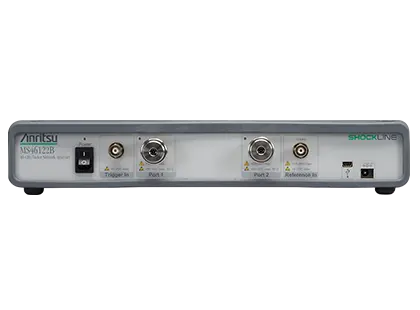
ShockLine MS46122B Compact USB 2-Port Vector Network Analyzer, 1 MHz to 8/20/43.5 GHz
Compact 1U, PC-controlled 2-port USB vector network analyzer covering 1 MHz to 8, 20 or 43.5 GHz depending on frequency option.
- Frequency range
- 1 MHz to 8 GHz
- Frequency range
- 1 MHz to 20 GHz
- Frequency range
- 1 MHz to 43.5 GHz
- Number of test ports
- 2
Overview
The ShockLine MS46122B is a compact, PC-controlled, full-reversing 2-port vector network analyzer (VNA) from Anritsu. It is offered in three frequency ranges, 1 MHz to 8 GHz, 20 GHz or 43.5 GHz, selected by a required frequency option, and performs S-parameter and time domain measurements.
The instrument is based on Anritsu's patented ShockLine VNA-on-chip technology, which simplifies the internal VNA architecture at high frequencies, lowers instrument cost and improves accuracy and measurement repeatability. It is aimed at RF and microwave passive device testing in manufacturing, engineering and education, including passive 5G mmWave components.
The MS46122B is housed in a 1U chassis, is controlled over USB from a user-supplied PC and is powered by an external power supply. It runs the same graphical user interface and driver software as the rest of the ShockLine VNA family. The unit has no on-board memory, which simplifies its use in secure areas.
Optional capabilities include time domain analysis with time gating (Option 2) and Universal Fixture Extraction (Option 24), which adds network extraction techniques for de-embedding test fixtures. IVI-C drivers support LabVIEW, LabWindows, C#, .NET, MATLAB and Python programming environments.
Key Features
- Guaranteed performance to 43.5 GHz with Extended K ports
- PC control takes advantage of external computer processing power and functionality
- Compact 1U high package for efficient use of bench and rack space
- No on-board data storage eliminates the need for data purging in secure applications
- Time domain with time gating option for faster fault identification
- Common GUI within the ShockLine family reduces switching costs between models
- Universal Fixture Extraction (UFX) software option provides advanced de-embedding tools for test fixture extraction
- Full-reversing 2-port S-parameter measurements
- Up to 16 channels, each with up to 16 traces
- Calibration methods include SOLT, SSLT, SSST, SOLR, LRL/LRM, TRL/TRM, SmartCal and AutoCal
- Embedding/de-embedding and O/E, E/O and O/O setup wizards
Specifications
|
Frequency range
MS46122B-010
|
1 MHz to 8 GHz |
|---|---|
|
Frequency range
MS46122B-020
|
1 MHz to 20 GHz |
|
Frequency range
MS46122B-043
|
1 MHz to 43.5 GHz |
| Number of test ports | 2 |
| 1 MHz to 10 MHz |
85 dB (105 dB typical)
High source power minus RMS noise floor at 10 Hz IF bandwidth with isolation calibration
|
|---|---|
| > 10 MHz to 8 GHz |
100 dB (115 dB typical)
Crosstalk may reduce dynamic range up to 20 dB (typical) at IF bandwidths ≤ 10 kHz when measuring highly reflective DUTs from 4 GHz to 8 GHz; reflection measurements not affected
|
| > 8 GHz to 40 GHz |
100 dB (110 dB typical)
Decrease specification by 5 dB between 8 GHz and 14 GHz
|
| > 40 GHz to 43.5 GHz | 97 dB (110 dB typical) |
| Receiver compression level, 1 MHz to 43.5 GHz |
+5 dBm
Port power beyond which response may be compressed more than 0.1 dB; characteristic
|
|---|---|
| High level noise, 1 MHz to < 20 MHz |
0.03 dB (0.005 dB typical); < 0.2 deg (< 0.035 deg typical)
Magnitude; phase. 100 Hz IF bandwidth, High power level, RMS; characteristic
|
| High level noise, 20 MHz to 20 GHz |
0.006 dB (0.001 dB typical); < 0.1 deg (< 0.05 deg typical)
Magnitude; phase
|
| High level noise, > 20 GHz to 40 GHz |
0.006 dB (0.001 dB typical); < 0.15 deg (< 0.05 deg typical)
Magnitude; phase
|
| High level noise, > 40 GHz to 43.5 GHz |
0.009 dB (0.001 dB typical); < 0.18 deg (< 0.05 deg typical)
Magnitude; phase
|
| Output power, High (default), 1 MHz to 8 GHz |
5 dBm
Typical
|
| Output power, High (default), > 8 GHz to 43.5 GHz |
–3 dBm
Typical
|
| Output power, Low, 1 MHz to 43.5 GHz |
–20 dBm
Typical
|
| Measurement stability, 10 MHz to 43.5 GHz |
0.02 dB/°C magnitude; 0.3 deg/°C phase
Ratio measurement with ports shorted; typical
|
| Resolution | 1 Hz |
|---|---|
| Accuracy |
± 1.0 ppm
At time of calibration
|
| Stability |
± 1.0 ppm from -10 °C to +55 °C
Typical
|
| Aging |
± 1.0 ppm/year
Typical
|
| Directivity, 1 MHz to 43.5 GHz |
> 8 dB
User and system correction off; typical
|
|---|---|
| Port match, 1 MHz to 43.5 GHz |
> 8 dB
User and system correction off; typical
|
|
1 MHz to 6 GHz
MS46122B-010
|
Directivity ≥ 42 dB; Source Match ≥ 33 dB; Load Match ≥ 42 dB; Reflection Tracking ±0.15 dB; Transmission Tracking ±0.06 dB
12-term SOLT with TOSLN50A-8 or TOSLNF50A-8; load match and tracking are characteristic
|
|---|---|
|
> 6 GHz to 8 GHz
MS46122B-010
|
Directivity ≥ 37 dB; Source Match ≥ 33 dB; Load Match ≥ 37 dB; Reflection Tracking ±0.15 dB; Transmission Tracking ±0.06 dB
12-term SOLT with TOSLN50A-8 or TOSLNF50A-8
|
|
1 MHz to 10 GHz
MS46122B-020
|
Directivity ≥ 42 dB; Source Match ≥ 33 dB; Load Match ≥ 42 dB; Reflection Tracking ±0.15 dB; Transmission Tracking ±0.06 dB
12-term SOLT with TOSLK50A-20 or TOSLKF50A-20
|
|
> 10 GHz to 20 GHz
MS46122B-020
|
Directivity ≥ 36 dB; Source Match ≥ 26 dB; Load Match ≥ 36 dB; Reflection Tracking ±0.15 dB; Transmission Tracking ±0.05 dB
12-term SOLT with TOSLK50A-20 or TOSLKF50A-20
|
|
1 MHz to 10 GHz
MS46122B-043
|
Directivity ≥ 42 dB; Source Match ≥ 33 dB; Load Match ≥ 42 dB; Reflection Tracking ±0.15 dB; Transmission Tracking ±0.06 dB
12-term SOLT with TOSLK50A-43.5 or TOSLKF50A-43.5, generic coefficients
|
|
> 10 GHz to 20 GHz
MS46122B-043
|
Directivity ≥ 36 dB; Source Match ≥ 26 dB; Load Match ≥ 36 dB; Reflection Tracking ±0.15 dB; Transmission Tracking ±0.06 dB
TOSLK50A-43.5 / TOSLKF50A-43.5, generic coefficients
|
|
> 20 GHz to 30 GHz
MS46122B-043
|
Directivity ≥ 32 dB; Source Match ≥ 22 dB; Load Match ≥ 32 dB; Reflection Tracking ±0.15 dB; Transmission Tracking ±0.06 dB
TOSLK50A-43.5 / TOSLKF50A-43.5, generic coefficients
|
|
> 30 GHz to 40 GHz
MS46122B-043
|
Directivity ≥ 30 dB; Source Match ≥ 20 dB; Load Match ≥ 30 dB; Reflection Tracking ±0.15 dB; Transmission Tracking ±0.06 dB
TOSLK50A-43.5 / TOSLKF50A-43.5, generic coefficients
|
|
> 40 GHz to 43.5 GHz
MS46122B-043
|
Directivity ≥ 28 dB; Source Match ≥ 20 dB; Load Match ≥ 28 dB; Reflection Tracking ±0.2 dB; Transmission Tracking ±0.16 dB
TOSLK50A-43.5 / TOSLKF50A-43.5, generic coefficients
|
|
> 40 GHz to 43.5 GHz, with .s1p definitions
MS46122B-043
|
Directivity ≥ 42 dB; Source Match ≥ 41 dB; Load Match ≥ 41 dB; Reflection Tracking ±0.2 dB; Transmission Tracking ±0.16 dB
TOSLK50A-43.5 / TOSLKF50A-43.5 with .s1p definitions; ≥ 45 dB directivity below 40 GHz
|
| Measurement speed |
140 µs/point, typical
300 kHz IFBW, 1601 points, 2-port calibrated; dependent on external PC. Web page states 130 µs/point typical
|
|---|
| 2-port measurements | S11, S21, S22, S12, and any user-defined combination of a1, a2, b1, b2, 1 |
|---|---|
| Domains | Frequency Domain, Time (Distance) Domain (Option 2) |
| Frequency sweep types | Linear, Log, CW, or Segmented |
| Maximum data points | 2 to 16,001 points |
| IF bandwidth | 10, 20, 50, 70, 100, 200, 300, 500, 700 Hz; 1, 2, 3, 5, 7, 10, 20, 30, 50, 70, 100, 200, 300 kHz |
| Averaging | Point-by-point, maximum 200 averages; sweep-by-sweep, maximum 4096 averages |
| Limit lines | Single or segmented. 2 limit lines per trace. 50 segments per trace. |
| Channels and traces | 16 channels, each with up to 16 traces |
| Markers | 12 markers + 1 reference marker |
| Circular graph types | Smith Chart (Impedance), Polar |
|
Test ports 1 and 2
MS46122B-010
|
N(f) |
|---|---|
|
Test ports 1 and 2
MS46122B-020
|
Ruggedized K(m) |
|
Test ports 1 and 2
MS46122B-043
|
Ruggedized Extended-K(m) |
| Damage input levels | +23 dBm maximum, ±50 VDC maximum |
| USB port | One mini type B USB port for connecting to an external PC controller |
| 10 MHz In |
BNC(f), +0 dBm, typical; 50Ω, nominal
Auto-sensing; better than 10 ppm frequency accuracy recommended
|
| External trigger input |
BNC(f), 0 to 3.3 V input (5 V tolerant), > 100 kΩ, 50 ns minimum pulse width
Trigger delay 6 µs typical
|
| CPU | Intel Core i5-6300U Processor |
|---|---|
| RAM | 4 GB |
| Disk | 120 GB |
| Operating system |
Windows 7, 8, 8.1, 10, or 11; 32- or 64-bit
DirectX 9 with WDDM installed
|
| Dimensions (H x W x D) |
61.1 mm x 328.1 mm x 197.87 mm
Instrument body without rack mount option
|
|---|---|
| Weight |
< 2.2 kg (< 5 lb)
Typical weight, fully-loaded
|
| Environmental class | MIL-PRF-28800F Class 3 |
|---|---|
| Operating temperature | 0 ºC to 50 ºC |
| Storage temperature | –40 ºC to 71 ºC |
| Maximum relative humidity | 95 % RH at 30 ºC, non-condensing |
| Altitude | 4600 meters, operating and non-operating |
| European Union | EMC 2014/30/EU, EN 61326:2013; Low Voltage Directive 2014/35/EU; Safety EN 61010-1:2010; RoHS 2011/65/EU & Amendment 2015/863 |
|---|---|
| Canada | CAN ICES-1(A)/NMB-1(A) |
| Australia and New Zealand | RCM AS/NZS 4417:2012 |
| Recommended calibration cycle | 12 months |
| Instrument warranty |
1 year from the date of shipment
Standard warranty; additional warranty available
|
Specifications are taken from the manufacturer's documentation. See the datasheet for complete and current values.
Applications
- RF and microwave connectors and cables
- Electromechanical switches
- Attenuators
- Couplers
- Filters
- Isolators
- Circulators
- Phase shifters
- System calibration
- Path-loss characterization
- General S-parameter and time domain measurements
- Secure area testing without on-unit data storage
- Wireless power transfer (KQ product, maximum efficiency)
- Passive 5G mmWave component testing
- Material measurements
Included
- Getting Started with Anritsu Flier
- 40-187-R, 12 V, 5 A power supply (and power cord)
- 3-2000RS-1815, USB 2.0 A to Mini B cable, 10 ft
- Bracket hardware for shelf-mounting into a 19 inch universal rack
Options & Accessories
| Option | Description |
|---|---|
| MS46122B-010 | 1 MHz to 8 GHz, type N(f) ports — Frequency option; select one frequency option only |
| MS46122B-020 | 1 MHz to 20 GHz, Ruggedized type K(m) ports — Compatible with 3.5 mm and SMA connectors; select one frequency option only |
| MS46122B-043 | 1 MHz to 43.5 GHz, Ruggedized type Extended-K(m) ports — Compatible with standard K (2.92 mm), 3.5 mm, and SMA connectors; select one frequency option only |
| MS46122B-002 | Time Domain with Time Gating — Low-pass and band-pass modes, phasor impulse, windowing, gating (pass-band or reject-band) |
| MS46122B-024 | Universal Fixture Extraction — Additional network extraction techniques for de-embedding fixtures |
| MS46122B-097 | Accredited Calibration, with data |
| MS46122B-098 | Standard Calibration, ISO 17025 compliant, without data |
| MS46122B-099 | Premium Calibration, ISO 17025 compliant, with data |
| MN25208A | 2-port USB SmartCal Module, 300 kHz to 8.5 GHz — Connector options -001 N(f), -002 K(f), -003 3.5 mm(f) |
| MN25408A | 4-port USB SmartCal Module, 300 kHz to 8.5 GHz |
| MN25218A | 2-port USB SmartCal Module, 300 kHz to 20 GHz — Connector option -002 K(f). Rev 2 modules; serial numbers <1817999 operate from 1 MHz to 20 GHz |
| MN25418A | 4-port USB SmartCal Module, 300 kHz to 20 GHz — Connector option -002 K(f) |
| 36585K-2M | K Connector Precision AutoCal Module, 70 kHz to 40 GHz, K(m) to K(m) |
| 36585K-2F | K Connector Precision AutoCal Module, 70 kHz to 40 GHz, K(f) to K(f) |
| 36585K-2MF | K Connector Precision AutoCal Module, 70 kHz to 40 GHz, K(m) to K(f) |
| 2000-1809-R | Serial to USB Adapter — Required for 36585 AutoCal module if control PC does not have a serial port |
| 3650A | SMA/3.5 mm Calibration Kit, Without Sliding Loads, DC to 26.5 GHz, 50 Ω |
| 3652A | K Connector Calibration Kit, Without Sliding Loads, DC to 40 GHz, 50 Ω |
| 3653A | N Connector Calibration Kit, Without Sliding Loads, DC to 18 GHz, 50 Ω |
| OSLN50A-8 | Precision N Male Open/Short/Load Mechanical Calibration Tee, DC to 8 GHz, 50 Ω |
| OSLNF50A-8 | Precision N Female Open/Short/Load Mechanical Calibration Tee, DC to 8 GHz, 50 Ω |
| TOSLN50A-8 | Precision N Male Through/Open/Short/Load Mechanical Calibration Tee, DC to 8 GHz, 50 Ω |
| TOSLNF50A-8 | Precision N Female Through/Open/Short/Load Mechanical Calibration Tee, DC to 8 GHz, 50 Ω |
| OSLN50A-18 | Precision N Male Open/Short/Load Mechanical Calibration Tee, DC to 18 GHz, 50 Ω |
| OSLNF50A-18 | Precision N Female Open/Short/Load Mechanical Calibration Tee, DC to 18 GHz, 50 Ω |
| TOSLN50A-18 | Precision N Male Through/Open/Short/Load Mechanical Calibration Tee, DC to 18 GHz, 50 Ω |
| TOSLNF50A-18 | Precision N Female Through/Open/Short/Load Mechanical Calibration Tee, DC to 18 GHz, 50 Ω |
| TOSLK50A-20 | Precision K Male Through/Open/Short/Load Mechanical Calibration Tee, DC to 20 GHz, 50 Ω |
| TOSLKF50A-20 | Precision K Female Through/Open/Short/Load Mechanical Calibration Tee, DC to 20 GHz, 50 Ω |
| TOSLK50A-40 | Precision K Male Through/Open/Short/Load Mechanical Calibration Tee, DC to 40 GHz, 50 Ω |
| TOSLKF50A-40 | Precision K Female Through/Open/Short/Load Mechanical Calibration Tee, DC to 40 GHz, 50 Ω |
| TOSLK50A-43.5 | Precision K Male Through/Open/Short/Load Mechanical Calibration Tee, DC to 43.5 GHz, 50 Ω — Includes .s1p files for data-based calibration support |
| TOSLKF50A-43.5 | Precision K Female Through/Open/Short/Load Mechanical Calibration Tee, DC to 43.5 GHz, 50 Ω — Includes .s1p files for data-based calibration support |
| 3663-3 | N Connector Verification Kit |
| 3668-4 | 43.5 GHz K Connector Verification Kit |
| 1091-26-R | Adapter, SMA(m) to N(m), DC to 18 GHz, 50 Ω |
| 1091-27-R | Adapter, SMA(f) to N(m), DC to 18 GHz, 50 Ω |
| 1091-80-R | Adapter, SMA(m) to N(f), DC to 18 GHz, 50 Ω |
| 1091-81-R | Adapter, SMA(f) to N(f), DC to 18 GHz, 50 Ω |
| 71693-R | Ruggedized adapter, K(f) to N(f), DC to 18 GHz, 50 Ω |
| 33KK50C | Calibration Grade Adapter, DC to 43.5 GHz, K(m) to K(m), 50 Ω |
| 33KKF50C | Calibration Grade Adapter, DC to 43.5 GHz, K(m) to K(f), 50 Ω |
| 33KFKF50C | Calibration Grade Adapter, DC to 43.5 GHz, K(f) to K(f), 50 Ω |
| 34NK50 | Precision Adapter, N(m) to K(m), DC to 18 GHz, 50 Ω |
| 34NKF50 | Precision Adapter, N(m) to K(f), DC to 18 GHz, 50 Ω |
| 34NFK50 | Precision Adapter, N(f) to K(m), DC to 18 GHz, 50 Ω |
| 34NFKF50 | Precision Adapter, N(f) to K(f), DC to 18 GHz, 50 Ω |
| 34VFK50A | Precision Adapter, DC to 43.5 GHz, V(f) - K(m), 50 Ω |
| 34VFKF50A | Precision Adapter, DC to 43.5 GHz, V(f) - K(f), 50 Ω |
| 34VK50A | Precision Adapter, DC to 43.5 GHz, V(m) - K(m), 50 Ω |
| 34VKF50A | Precision Adapter, DC to 43.5 GHz, V(m) - K(f), 50 Ω |
| K220B | Precision Adapter, DC to 40 GHz, K(m) to K(m), 50 Ω |
| K222B | Precision Adapter, DC to 40 GHz, K(f) to K(f), 50 Ω |
| K224B | Precision Adapter, DC to 40 GHz, K(m) to K(f), 50 Ω |
| 15NNF50-1.0B | Test Port Cable, Flexible, Phase Stable, N(f) to N(m), 1.0 m |
| 15NNF50-1.5B | Test Port Cable, Flexible, Phase Stable, N(f) to N(m), 1.5 m |
| 15NN50-1.0B | Test Port Cable, Flexible, Phase Stable, N(m) to N(m), 1.0 m |
| 15LL50-1.0A | Test Port Extension Cable, Armored, Phase Stable, DC to 26.5 GHz, 3.5 mm(m) to 3.5 mm(m), 1.0 m, 50 Ω — Web page lists DC to 20 GHz; datasheet value used |
| 15LLF50-1.0A | Test Port Extension Cable, Armored, Phase Stable, DC to 26.5 GHz, 3.5 mm(m) to 3.5 mm(f), 1.0 m, 50 Ω |
| 15KK50-1.0A | Test Port Extension Cable, Armored, Phase Stable, DC to 26.5 GHz, K(m) to K(m), 1.0 m, 50 Ω |
| 15KKF50-1.0A | Test Port Extension Cable, Armored, Phase Stable, DC to 26.5 GHz, K(m) to K(f), 1.0 m, 50 Ω |
| 3670N50-1 | Semi-rigid armored cable, 0.3 m (12”), DC to 18 GHz, N(f) to N(m), 50 Ω |
| 3670NN50-1 | Semi-rigid armored cable, 0.3 m (12”), DC to 18 GHz, N(m) to N(m), 50 Ω |
| 3670N50-2 | Semi-rigid armored cable, 0.6 m (24”), DC to 18 GHz, N(f) to N(m), 50 Ω |
| 3670NN50-2 | Semi-rigid armored cable, 0.6 m (24”), DC to 18 GHz, N(m) to N(m), 50 Ω |
| 3670K50A-1 | Semi-rigid armored cable, 0.3 m (12”), DC to 43.5 GHz, K(f) to K(m), 50 Ω |
| 3670K50A-2 | Semi-rigid armored cable, 0.6 m (24”), DC to 43.5 GHz, K(f) to K(m), 50 Ω |
| 3671KFS50-60 | Flexible test port cable, 60 cm (23.6 in), DC to 20 GHz, K(f) to 3.5 mm(m), 50 Ω |
| 3671KFSF50-60 | Flexible test port cable, 60 cm (23.6 in), DC to 20 GHz, K(f) to 3.5 mm(f), 50 Ω |
| 3671KFKF50-60 | Flexible test port cable, 60 cm (23.6 in), DC to 40 GHz, K(f) to K(f), 50 Ω |
| 3671KFK50-100 | Flexible test port cable, 100 cm (39.4 in), DC to 40 GHz, K(f) to K(m), 50 Ω |
| 806-304-R | Flexible phase stable cable, 91.5 cm (36 in), DC to 40 GHz, K(m) to K(f), 50 Ω |
| 806-423-R | Flexible phase stable cable, 60 cm (23.6 in), DC to 43.5 GHz, K(f) - K(f), 50 Ω |
| 806-424-R | Flexible phase stable cable, 60 cm (23.6 in), DC to 43.5 GHz, K(m) - K(f), 50 Ω |
| 806-425-R | Flexible phase stable cable, 100 cm (39.4 in), DC to 43.5 GHz, K(f) - K(f), 50 Ω |
| 806-426-R | Flexible phase stable cable, 100 cm (39.4 in), DC to 43.5 GHz, K(m) - K(f), 50 Ω |
| 01-200 | Calibrated Torque End Wrench, GPC-7 and Type N |
| 01-201 | Torque End Wrench, 5/16 in, 0.9 N·m (8 lbf·in) — For tightening male devices, for SMA, 3.5 mm, 2.4 mm, K, and V connectors |
| 01-203 | Torque End Wrench, 13/16 in, 0.9 N·m (8 lbf·in) — For tightening ruggedized SMA, 2.4 mm, K and V test port connectors |
| 01-204 | End Wrench, 5/16 in, Universal, Circular, Open-ended — For SMA, 3.5 mm, 2.4 mm, K, and V connectors |