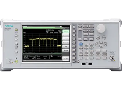
Anritsu MS2850A Signal Analyzer/Spectrum Analyzer with 1 GHz Analysis Bandwidth
Benchtop signal/spectrum analyzer covering 9 kHz to 32 GHz or 44.5 GHz with up to 1 GHz analysis bandwidth for 5G and satellite signals.
- Frequency range
- 9 kHz to 32 GHz
- Frequency range
- 9 kHz to 44.5 GHz
- Frequency range, Signal Analyzer mode (Bandwidth >31.25 MHz)
- 800 MHz to 32 GHz
- Frequency range, Signal Analyzer mode (Bandwidth >31.25 MHz)
- 800 MHz to 44.5 GHz
Overview
The Anritsu MS2850A is a benchtop spectrum analyzer/signal analyzer with a maximum analysis bandwidth of 1 GHz and a frequency range of 9 kHz to either 32 GHz (MS2850A-047) or 44.5 GHz (MS2850A-046). It is intended for wideband communications measurements such as 5G mobile and broadcast satellite equipment, covering sub-6 GHz through the millimeter-wave 28 GHz and 39 GHz bands.
The standard analysis bandwidth is 255 MHz, with 510 MHz and 1 GHz available as options. The FFT-based signal analyzer function provides spectrum, spectrogram, power vs. time, frequency vs. time, phase vs. time and CCDF/APD displays. Using the 32 GB internal memory, signals can be captured for up to 24 seconds at a 100 MHz span and replayed later for analysis in different display modes.
Dynamic range and flatness
A high ADC clipping level over the 1 GHz analysis bandwidth gives a wide difference from the displayed average noise level, which supports accurate EVM measurement of 5G signals. In the 28 GHz band the measured dynamic range between ADC clipping level and DANL is 142 dB (ref.). In-band amplitude and phase flatness are specified for wideband per-carrier amplitude and phase measurements.
5G measurement and data transfer
Optional MX285051A 5G measurement software covers V5G pre-standard and 5G NR (sub-6 GHz and mmWave) uplink and downlink, including batch analysis of up to eight 100 MHz carriers with the 1 GHz bandwidth option. Optional PCIe and USB 3.0 interfaces transfer captured IQ data to an external PC faster than 1000BASE-T for analysis with general EDA tools.
Key Features
- Built-in 5G measurement software support for V5G and 5G NR (sub-6 GHz/mmWave)
- Residual EVM better than 1% in combination with the 5G measurement software
- One-button Auto Range dynamic-range optimization for EVM measurement
- Multicarrier batch (all-at-once) analysis of up to 8 carriers × 100 MHz
- Amplitude, phase and timing difference measurement for each carrier
- Maximum analysis bandwidth of 1 GHz (255 MHz standard, 510 MHz and 1 GHz options)
- Amplitude and phase flatness specified over 1 GHz analysis bandwidth
- Wide measurement dynamic range of more than 140 dB
- Long-term capture using 32 GB memory, up to 24 s at 100 MHz span
- Capture & Replay with switchable display modes
- Optional PCIe/USB3.0 interface for high-speed transfer of captured data
- Microwave preselector bypass as standard function
- USB power sensor connection as standard function
- 2 dB step input attenuator
Specifications
|
Frequency range
MS2850A-047
|
9 kHz to 32 GHz
Spectrum Analyzer mode, Signal Analyzer mode (Bandwidth ≤31.25 MHz)
|
|---|---|
|
Frequency range
MS2850A-046
|
9 kHz to 44.5 GHz
Spectrum Analyzer mode, Signal Analyzer mode (Bandwidth ≤31.25 MHz)
|
|
Frequency range, Signal Analyzer mode (Bandwidth >31.25 MHz)
MS2850A-047
|
800 MHz to 32 GHz |
|
Frequency range, Signal Analyzer mode (Bandwidth >31.25 MHz)
MS2850A-046
|
800 MHz to 44.5 GHz |
|
Frequency setting range
MS2850A-047
|
−100 MHz to 32.5 GHz
Setting resolution 1 Hz
|
|
Frequency setting range
MS2850A-046
|
−100 MHz to 45 GHz
Setting resolution 1 Hz
|
|
Span setting range
MS2850A-047
|
0 Hz, 300 Hz to 32 GHz
Setting resolution 2 Hz
|
|
Span setting range
MS2850A-046
|
0 Hz, 300 Hz to 44.5 GHz
Setting resolution 2 Hz
|
| Span accuracy |
±0.2%
Trace Point 10,001
|
| Resolution bandwidth (RBW) |
1 Hz to 3 MHz (1-3 sequence), 500 Hz, 50 kHz, 2 MHz, 5 MHz, 10 MHz
1 Hz to 10 Hz: Can not be set when SPAN 0 Hz
|
| RBW selectivity (−60 dB/−3 dB) |
4.5: 1
1 Hz to 10 MHz, nom.
|
| Video bandwidth (VBW) | 1 Hz to 3 kHz (1-3 sequence), 5 kHz, 10 kHz to 10 MHz (1-3 sequence), Off |
| Start-up characteristics |
±5 × 10⁻⁷ (2 minutes after power-on), ±5 × 10⁻⁸ (5 minutes after power-on)
Based on frequency 24 hours after power-on, at 23°C
|
|---|---|
| Aging rate | ±1 × 10⁻⁷ /year |
| Temperature characteristics | ±2 × 10⁻⁸ (0°C to +45°C) |
| Frequency accuracy at the initial calibration |
±2.2 × 10⁻⁸
18°C to 28°C, 1 hour after power-on
|
| 10 kHz offset |
−123 dBc/Hz
18º to 28°C, Center frequency 1 GHz, Spectrum Analyzer mode; 95th percentile −127 dBc/Hz
|
|---|---|
| 100 kHz offset |
−123 dBc/Hz
Center frequency 1 GHz; 95th percentile −126 dBc/Hz
|
| 1 MHz offset |
−135 dBc/Hz
Center frequency 1 GHz; 95th percentile −136 dBc/Hz
|
| 10 MHz offset |
−148 dBc/Hz
Center frequency 1 GHz, nom.
|
| Level measurement range |
DANL to +30 dBm
Without MS2850A-068 or Preamp Off
|
|---|---|
|
Level measurement range
MS2850A-068
|
DANL to +10 dBm
With MS2850A-068 and Preamp On
|
| Maximum input level (average total power) |
+30 dBm
Input attenuator ≥10 dB; +20 dBm at 0 dB; without MS2850A-068 or Preamp Off; DC voltage ±0 Vdc
|
| Input attenuator range | 0 to 60 dB, 2 dB Steps |
| Reference level setting range |
Log scale: –120 to +50 dBm; Linear scale: 22.4 μV to 70.7 V
Or equivalent level; setting resolution 0.01 dB
|
| Linearity error |
±0.07 dB
Mixer input level ≤−20 dBm, without MS2850A-068 or Preamp Off, Bandwidth ≤31.25 MHz
|
| RF frequency characteristics, 50 MHz ≤ frequency < 4 GHz |
±0.35 dB
Spectrum Analyzer mode, Preselector Bypass Off, Preamp Off, 18°C to 28°C, Input attenuator 10 dB
|
| 30 MHz ≤ frequency < 1 GHz |
−153 dBm/Hz
Without MS2850A-068, Detector Sample, VBW 1 Hz, Input attenuator 0 dB
|
|---|---|
| 26.5 GHz < frequency ≤ 34 GHz |
−140 dBm/Hz
Without MS2850A-068
|
| 40 GHz < frequency ≤ 44.5 GHz |
−130 dBm/Hz (nom.)
Without MS2850A-068
|
|
30 MHz ≤ frequency < 1 GHz, Preamp On
MS2850A-068
|
−166 dBm/Hz
With MS2850A-068 and Preamp On; 95th percentile −168 dBm/Hz
|
| 1 MHz ≤ frequency ≤ 1 GHz |
≤−100 dBm
Input attenuator 0 dB, 50Ω terminated
|
|---|---|
| 1 GHz < frequency ≤ 6 GHz | ≤−90 dBm (typ.) |
| 26.5 GHz < frequency ≤ 44.5 GHz | ≤−80 dBm (nom.) |
|
Analysis bandwidth
MS2850A-032
|
255 MHz (Standard)
Frequency measurement range 100 MHz to 32 GHz/44.5 GHz
|
|---|---|
|
Analysis bandwidth
MS2850A-033
|
510 MHz (option)
Frequency measurement range 100 MHz to 32 GHz/44.5 GHz
|
|
Analysis bandwidth
MS2850A-034
|
1 GHz (option)
Frequency measurement range 4.2 GHz to 32 GHz/44.5 GHz
|
| In-band frequency characteristics |
±1.2 dB (nom.)
Center Frequency 28 GHz, at Center Frequency ±500 MHz
|
| In-band phase linearity |
5 deg. p-p (nom.)
Center Frequency 28 GHz, at Center Frequency ±500 MHz
|
| SFDR, 800 MHz ≤ Frequency < 4.2 GHz | -60 dBc (nom.) |
| SFDR, 4.2 GHz ≤ Frequency ≤ 44.5 GHz | -70 dBc (nom.) |
| ADC clipping level |
0 dBm (CW)
Center Frequency 28 GHz; meas., not guaranteed
|
| Dynamic range |
142 dB (ref.)
Center Frequency 28 GHz, difference between ADC clipping level and DANL (−142 dBm/Hz, meas.)
|
| Max. capture time, 100 MHz span |
24 s
Sampling rate 162.5 MHz
|
| Max. capture time, 1000 MHz span |
3 s
Sampling rate 1300 MHz
|
Specifications are taken from the manufacturer's documentation. See the datasheet for complete and current values.
Applications
- 5G NR base station and terminal transmitter testing
- Broadcast satellite equipment evaluation
- Microwave and millimeter-wave wideband communications R&D
- Production testing of communications equipment
- O-RAN O-RU RF transmitter testing
- Phased-array antenna phase measurement
- Millimeter-wave and automotive radar measurement with external mixers
- LTE/LTE-Advanced, W-CDMA and GSM transmitter measurement
Options & Accessories
| Option | Description |
|---|---|
| MS2850A-047 | 9 kHz to 32 GHz |
| MS2850A-046 | 9 kHz to 44.5 GHz |
| MS2850A-010 | Phase Noise Measurement Function — Measures phase noise over a frequency offset of 10 Hz to 10 MHz |
| MS2850A-011 | Secondary Storage Device — Removable SSD extending internal storage for large digitized data files |
| MS2850A-014 | Removable SSD, Win10 — User-changeable SSD with the same Windows OS and programs as the factory system SSD, for service repair and calibration |
| MS2850A-017 | Noise Figure Measurement Function — Y-Factor noise figure measurement using Noisecom NC346 series noise sources |
| MS2850A-032 | Analysis Bandwidth 255 MHz (Standard) |
| MS2850A-033 | Analysis Bandwidth Extension 510 MHz |
| MS2850A-034 | Analysis Bandwidth Extension 1 GHz |
| MS2850A-051 | Noise Floor Reduction — Subtracts internal noise components (11 dB max. nominal) from the displayed result |
| MS2850A-053 | External Interface for High Speed Data Transfer PCIe |
| MS2850A-054 | External Interface for High Speed Data Transfer USB3.0 |
| MS2850A-067 | Microwave Preselector Bypass (Standard) |
| MS2850A-068 | Microwave Preamplifier — 20 dB gain preamplifier improving DANL |
| MS2850A-072 | Extended Specifications |
| MS2850A-076 | Low Second Harmonic Distortion — Upgrades second harmonic distortion performance for input frequencies of 2 GHz to 22.25 GHz |
| MX285051A | 5G Standard Measurement Software (Base License) |
| MX285051A-001 | Pre-Standard CP-OFDM Downlink |
| MX285051A-051 | Pre-Standard CP-OFDM Uplink |
| MX285051A-011 | NR TDD sub-6 GHz Downlink |
| MX285051A-061 | NR TDD sub-6 GHz Uplink |
| MX285051A-031 | NR FDD sub-6 GHz Downlink |
| MX285051A-081 | NR FDD sub-6 GHz Uplink |
| MX285051A-021 | NR TDD mmWave Downlink |
| MX285051A-071 | NR TDD mmWave Uplink |
| MX269011A | W-CDMA/HSPA Downlink Measurement Software |
| MX269012A | W-CDMA/HSPA Uplink Measurement Software |
| MX269013A | GSM/EDGE Measurement Software |
| MX269013A-001 | EDGE Evolution Measurement Software |
| MX269020A | LTE Downlink Measurement Software |
| MX269020A-001 | LTE-Advanced FDD Downlink Measurement Software |
| MX269022A | LTE TDD Downlink Measurement Software |
| MX269022A-001 | LTE-Advanced TDD Downlink Measurement Software |
| MX269021A | LTE Uplink Measurement Software |
| MX269021A-001 | LTE-Advanced FDD Uplink Measurement Software |
| MX269023A | LTE TDD Uplink Measurement Software |
| MX269023A-001 | LTE-Advanced TDD Uplink Measurement Software |
| MX269017A | Vector Signal Analysis Software |
| MX269017A-001 | APSK Analysis — 16APSK, 32APSK |
| MX269017A-011 | Higher-Order QAM Analysis — 512QAM, 1024QAM, 2048QAM |
| MX284090A | External Mixer Connection Function — Wideband millimeter-wave measurement using Eravant and VDI external mixers |