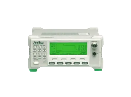
Anritsu ML2437A Single-Input CW Power Meter (ML2430A Series)
Single-input ML2430A series CW power meter with graphics display, 90 dB dynamic range with a single sensor and optional NiMH battery.
- Display
- Monochrome LCD, with backlight and adjustable contrast
- Display Resolution in Readout Mode
- 0.1 dB to 0.001 dB; Linear power units, 3 to 6 digits, 1 to 3 digits selectable to right of decimal, nW to W; Voltage, 1 to 2 digits selectable to right of decimal
- Display Resolution in Profile Mode
- 0.01 dB
- Time Measurement Resolution
- 200 pixels display resolution
Overview
The Anritsu ML2437A is the single-input model of the ML2430A series of power meters, which are designed for CW applications. It combines thermal meter accuracy, diode meter speed and peak power meter display graphics in one instrument that samples at more than 35K per second and achieves 90 dB dynamic range with a single sensor.
A graphics display is a standard feature. The meter can show a time-domain profile of pulsed signals or a strip-chart style power versus time display of pulsed power or TDMA signals, and frame triggering allows the average power across a time slot to be measured.
The ruggedized polycarbonate housing is portable and splash resistant, and an optional high-capacity NiMH battery supports field service use. A rear panel BNC input measures voltage or accepts a V/GHz signal for automated sensor calibration factor correction.
Remote operation and software
The meter is controlled over GPIB or RS232 and emulates older meters, including the Anritsu ML4803 and Agilent 436, 437 and 438. In profile mode it can measure and transfer a burst of 200 data points. PowerSuite, free software for the ML2430A series, displays measurement traces on a PC in real time and archives data and plots for later analysis.
Key Features
- Graphics display capability included as standard
- 90 dB dynamic range with a single sensor
- Portable, rugged and splash-resistant polycarbonate chassis
- Optional NiMH battery providing six hours of continuous operation
- Profile operating mode measures and transfers a high-speed burst of 200 data points
- 99.9% emulation of older meters for ATE systems
- Typical test system speed improvement of 2 to 10 times
- Operator control of triggering delay and sample integration time per reading
- Trigger sources include continuous, internal, external TTL and manual
- Burst profile display of pulsed signals over a power range of –40 dBm to +20 dBm
- Pulse-top power measurement using between-cursor averaging
- Power versus time strip-chart display of pulsed power or TDMA signals
- Frame triggering to measure average power across a time slot
- Rear panel BNC voltage input for voltage measurement or V/GHz calibration factor correction
- Softkey menu control with numerical keypad
- Secure mode that wipes non-volatile memory on power up
- Remote monitoring with modem dial-out when a limit threshold is exceeded
Specifications
| Display | Monochrome LCD, with backlight and adjustable contrast |
|---|---|
| Display Resolution in Readout Mode | 0.1 dB to 0.001 dB; Linear power units, 3 to 6 digits, 1 to 3 digits selectable to right of decimal, nW to W; Voltage, 1 to 2 digits selectable to right of decimal |
| Display Resolution in Profile Mode | 0.01 dB |
| Time Measurement Resolution |
200 pixels display resolution
Profile and P vs. T modes; for a 1 ms Profile window, cursor resolution on the display is 5 µs
|
| Measurement Hold | Hold, Max, Min |
| Measurements | Average, Min, Max |
| Voltage Measurement Range | 0.00 to 20.00 V nominal |
| Display Units | Watt, %, Volts, dBm, dB, dBµV, dBmV, dBr |
| Display Range | –199.99 dB to +199.99 dB |
| Measurement Gates | 1 |
| Markers | 2 |
| Limit Lines |
Fixed value high and low limits with audible, rear panel TTL output, and/or visible Pass/Fail alarm indication
Failure indication can latch for transient failure detection
|
| Offset Range |
–199.99 dB to +199.99 dB
Fixed value or frequency dependent table
|
| Measurement Display Readout (Numerical) | 2 |
| Measurement Display Profile (Graph) | Power vs. Time graphic of readout data or Profile of Peak power for analysis of repetitive pulse or transient waveforms |
| Source Sweep | Single channel power sweep or frequency sweep |
| Peaking Meter |
± 5 dB range
CW (Readout mode) only
|
| Amplifier Range |
Dynamic range covered by five overlapping amplifier ranges: R1, R2, R3, R4, and R5
Universal Sensor MA2481/82D ranges 1 to 6
|
| Range Hold | Auto or Manual (current range or selectable 1 through 5) |
|
Number of Input Signals
ML2437A
|
1 |
|---|---|
| Frequency Range |
100 kHz to 50 GHz (sensor dependent)
The product page summary lists 100 kHz — 65 GHz; datasheet value shown
|
| Dynamic Range (Continuous or Peak) |
–70 to +20 dBm
Dependent on sensor, external coupler, or attenuator
|
| Nominal Video BW |
100 kHz
Profile mode
|
| Sampling Rate |
31.25 kS/s
Product page states sampling at more than 35K per second; datasheet value shown
|
| Instrumentation Accuracy, CW Mode | < 0.5% (± 0.02 dB absolute Accuracy, ± 0.04 dB Relative Accuracy) |
| Instrumentation Accuracy, Pulse/Modulated Mode |
< 0.8%
Nominal range 7, 8
|
| Averaging Type | Auto (Moving), Manual (Moving, Repeat) |
| Averaging Range | 1 to 512 |
| Low-level Averaging |
Low, Medium, and High settings
Apply post average low-pass filter to improve visibility at high display resolution
|
| Trigger Source | Internal, External (TTL or RF Blanking), GPIB, Manual, or Continuous |
|---|---|
| Trigger Modes | Manual: single power value set to cover entire measurement dynamic range of sensor; Auto: automatically sets trigger level for signal over measurement dynamic range |
| Internal Trigger Dynamic Range |
–15 dBm to +20 dBm
All diode sensors, selectable to –25 dBm
|
| Internal Trigger Level Accuracy |
1 dB
Typical
|
| Internal Trigger Settable Resolution | 0.1 dB |
| Trigger Delay Range | 0 ms to 999 ms |
| External Trigger Range | TTL rising or falling edge (BNC input) |
| Trigger Delay Settable Resolution | 0.5% of display period or 100 ns |
| Trigger/Display Capture Range | Profile mode: 10 ms to 7 s; P v T mode: 1 m to 24 hrs |
| Trigger Point Display | On-screen indicator/message |
| Reference Calibrator Power | 1 mW |
|---|---|
| Power Accuracy |
± 1.2% per year
Traceable to National Standards
|
| Frequency | 50 MHz (nominal) |
| Frequency Accuracy | < 1% |
| VSWR | < 1.12 |
| Connector Type | N female |
| Impedance | Nominal input impedance is 50 ohms |
| Save/Recall | 10 storage registers plus RESET default settings |
|---|---|
| Secure Mode | Wipes non-volatile memory on power up when active |
| Remote Monitoring | Yes |
| Modem Compatibility | Yes |
| GPIB (IEEE–488.2, IEC–625) | > 600 readings/second (per input channel) |
| GPIB Emulation | Emulation of Anritsu ML4803, Agilent 436, 437, and 438 |
| Parallel Printer Port | Compatible with Deskjet 540 and 340 Models (other 500 Series and 300 Series and later are typically compatible). Canon BJC 80. |
| RS232 |
Supports software download, instrument control, and modem dial-out
1200, 2400, 4800, 9600, 19200, 38400, 57600 Baud rates are supported
|
| Cal Factor Voltage Input (BNC) |
Input Range: 0 V to 20 V; Resolution: 0.5 mV
Display voltage reading on selected channel or voltage proportional to frequency for sensor calibration factor compensation; Blanking Input TTL levels only, selectable polarity
|
| External Trigger (BNC) | TTL, maximum frequency of 800 kHz |
| Analog Output (BNC) |
Two outputs configurable to Log or Lin; Output Range: –5.0 V to +5.0 V; Resolution: 0.1 mV
Modes: corrected channel reading, Pass/Fail TTL, near real time uncalibrated channel output, AC modulation output (Output 1 only), dwell output (Output 2 only)
|
| Non-Volatile RAM Battery | Lithium (10 year life) |
|---|---|
| Battery Option | > 6 hr usable with 3000 mAhr (NiMH) battery |
| DC Power Requirements | 12 to 24 VDC, Reverse protected to –40 V Maximum input 30 V |
| AC Power Requirements |
85 VAC to 240 VAC, 47 Hz to 400 Hz, 40 VA Maximum
No AC mains connection to measurement circuits. Quick Fact Sheet lists 90 to 250 VAC, 47 to 440 Hz; datasheet value shown
|
| Operating Temperature |
0 °C to 40 °C
Quick Fact Sheet lists 0° to 50 °C; datasheet value shown
|
|---|---|
| Operating Elevation |
4,600 m
Per W31P4Q-18-007
|
| Environment | For indoor use only, Pollution Degree 2 |
| Storage Temperature | –40 °C to 70 °C |
| Moisture | Splash and rain resistant, 95% humidity non-condensing |
| Military Compliance | MIL-T-28800F, class 3 |
| Dimensions |
223 mm x 150 mm x 390 mm
Quick Fact Sheet lists 213 mm W x 88 mm H x 390 mm D; datasheet value shown
|
|---|---|
| Weight |
3 kg
Excluding battery option
|
| Grounding Post | Used as safety ground when operating from DC or battery power |
| Warranty |
Power meters have a standard 1 year warranty
Quick Fact Sheet states 3-year standard for all Power Meters; datasheet value shown
|
| European Union EMC |
2014/30/EU, EN 61326-1:2013
CISPR 11/EN 55011, IEC/EN 61000-4-2/3/4/5/6/8/11
|
|---|---|
| Low Voltage Directive | 2014/35/EU |
| Safety | EN 61010-1:2010 |
| RoHS Directive | 2011/65/EU & 2015/863 |
| Australia and New Zealand | RCM AS/NZS 4417:2012 |
| South Korea | KCC-REM-A21+-0004 |
| Canada | ICES-1(A)/NMB-1(A) |
Specifications are taken from the manufacturer's documentation. See the datasheet for complete and current values.
Applications
- CW power measurement
- Field service
- Automated test equipment (ATE) systems
- Cellular and PCS burst power profiling (TDMA, PHS, GSM, DCS-1800)
- Mobile telephone power control troubleshooting
- Remote power monitoring
Included
- Power cord for destination country
- One 1.5 m sensor cord per meter input
- Certificate of Calibration
- PowerSuite software
- Operation Manual (soft copy)
- Programming Manual (soft copy)
Options & Accessories
| Option | Description |
|---|---|
| ML2400A-05 | Front Bail Handle |
| ML2400A-06 | Rear Mount Input A on ML2437A — Options 6, 7, 8 and 9 are mutually exclusive for any given ML2430A unit |
| ML2400A-07 | Rear Input A and Reference on ML2437A — Options 6, 7, 8 and 9 are mutually exclusive for any given ML2430A unit |
| ML2400A-98 | Calibration to ISO 17025 and/or ANSI/NCSL Z540 |
| ML2400A-99 | Premium Calibration |
| 2000-1603 | NiMH Battery |
| 2000-996-R | Desktop Battery Charger with Power Supply |
| 2000-1534-R | Desktop Battery Charger (for use in Japan only) |
| 2000-1545 | Bulkhead Adapter |
| 10585-00001 | Hard Copy Operation and Programming Manuals |
| 10585-00003 | Hard Copy Maintenance Manual |
| D41310 | Soft Carry Case with Shoulder Strap |
| 760-209 | Hardside Transit Case |
| 2000-1535 | Front Panel Cover |
| 2400-82 | Rack Mount, Single Unit — Options 5, 2400-82, and 2400-83 are mutually exclusive |
| 2400-83 | Rack Mount, Side-by-Side — Options 5, 2400-82, and 2400-83 are mutually exclusive |
| 2000-1536-R | 0.3 m Sensor Cable |
| 2000-1537-R | 1.5 m Sensor Cable — Standard sensor cable; peak and pulse sensor performance is specified with this cable |
| 2000-1538-R | 3 m Sensor Cable |
| 2000-1539-R | 5 m Sensor Cable |
| 2000-1540-R | 10 m Sensor Cable |
| 2000-1541-R | 30 m Sensor Cable |
| 2000-1542-R | 50 m Sensor Cable |
| 2000-1543-R | 100 m Sensor Cable |
| 2000-1544 | RS-232 Bootload Cable |