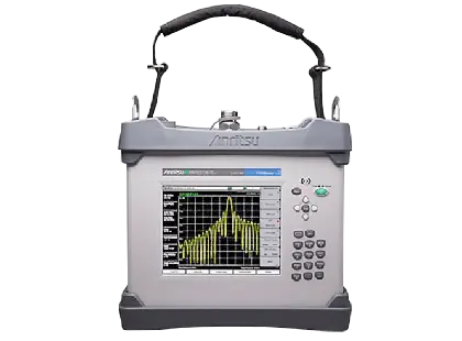
PIM Master MW82119B Battery-Operated Passive Intermodulation Analyzer with Optional Site Master Cable and Antenna Analyzer
Battery-operated 40 W portable PIM analyzer with optional Site Master cable and antenna analyzer for field certification of cell sites.
- PIM Test Port
- 7/16 DIN, female, 50Ω
- Dual USB Type A
- 2x Type A (connect USB Flash Drive and USB Power Sensor)
- USB Mini-B
- 1x Mini-B (connect to PC for data transfer)
- GPS
- SMA, female
Overview
The Anritsu PIM Master MW82119B is a battery-operated, portable Passive Intermodulation (PIM) analyzer with a test power of up to 40 W (46 dBm). With the Site Master Cable and Antenna Analyzer option (Option 331) installed, a single instrument measures PIM, Distance-to-PIM, Return Loss, VSWR, Cable Loss and Distance-to-Fault, so a cable and antenna system can be certified for both PIM and line sweep performance.
The instrument has a large, daylight-viewable touch screen display and a menu-driven user interface designed for field conditions. Its rugged, portable construction allows PIM and line sweep testing at the top of the tower, next to LTE Remote Radio Head (RRH) installations.
Cable and antenna systems are a critical link in a wireless network. The quality of the deployed components and of their installation affects network performance and site reliability. To work as intended, the system must pass RF signals between subscribers and the base station with minimum loss and minimum reflections, and without generating unwanted noise in the form of passive intermodulation.
Measurements
PIM measurements include PIM vs. Time, Swept PIM, Distance-to-PIM (DTP) and Noise Floor, with 3rd, 5th and 7th order intermodulation products detected. DTP locates PIM faults both inside the feed system and beyond the antenna, and trace overlay allows the active DTP trace to be compared with a stored DTP or DTF trace. The Site Master option adds the single-port measurement capabilities of a Site Master S331E, including OSL and FlexCal calibration and RF immunity for measurements near co-located sites.
Software and connectivity
The PIM Master works with Line Sweep Tools for trace management and report generation, and with the Multiwave Smart Aligner Android application for site close-out reports that combine antenna alignment and line sweep results. The instrument can be controlled through a web browser over Ethernet or a third-party Wi-Fi router, and programmed remotely using SCPI commands over USB or LAN.
Key Features
- Battery-operated Passive Intermodulation (PIM) analyzer
- Battery operation of more than 3 hours
- Test power from 20 dBm (0.1 W) to 46 dBm (40 W)
- PIM vs. Time, Swept PIM, Distance-to-PIM (DTP) and Noise Floor measurements
- 3rd, 5th and 7th order intermodulation products detected
- Residual PIM of –125 dBm typical
- Optional Site Master cable and antenna analyzer, 2 MHz to 3 GHz (Option 331)
- DTP/DTP and DTP/DTF trace overlay
- 8.4 in (213 mm) daylight-viewable touch screen
- IP54 rated for dust and water spray
- MIL-STD-810G drop test rated
- Stainless steel lifting rings
- Quick Name Matrix for file naming in the field
- GPS tagging of measurements (Option 31)
- High Accuracy Power Meter with USB power sensors (Option 19)
- 2-Port PIM testing with Option 703
- Supported by the Multiwave Smart Aligner Android application
- Standard three-year warranty (one-year warranty on battery)
Specifications
| PIM Test Port | 7/16 DIN, female, 50Ω |
|---|---|
| Dual USB Type A | 2x Type A (connect USB Flash Drive and USB Power Sensor) |
| USB Mini-B | 1x Mini-B (connect to PC for data transfer) |
|
GPS
MW82119B-0031
|
SMA, female
With GPS option only
|
| External Power | 2.1 mm x 5.5 mm barrel connector, 12 VDC to 15 VDC, < 5.0 A |
| PIM Test Port Damage Level |
+10 dBm (10 mW) continuous, (PIM Rx band); +35 dBm (3 W) continuous, (PIM Tx band)
Able to survive full reflection of 2 X 46 dBm PIM test tones generated by the MW82119B
|
|
1900 MHz In Test Port
MW82119B-0600
|
Type N, Female, 50Ω |
|
1900 MHz In Test Port Damage Level
MW82119B-0600
|
+10 dBm (10 mW) continuous, 1900 MHz Rx band |
|
VNA Test Port
MW82119B-0331
|
Type N, female, 50Ω |
|
VNA Test Port Damage Level
MW82119B-0331
|
40 dBm continuous |
|
PIM Test Port 2
MW82119B-0703
|
4.3-10 |
|
Port 2 Return
MW82119B-0703
|
SMA |
| Size |
213 mm (8.4 in) touch screen
Daylight viewable
|
|---|---|
| Resolution | 800 x 600 |
| Pixel Defects | No more than five defective pixels (99.9989% good pixels) |
| Battery Type | Li-Ion |
|---|---|
| Battery Operation | 3.0 hours, typical |
| Charging Limits | While charging, battery must be 0 °C to +45 °C, Relative Humidity ≤80 % |
| AC/DC Adapter | Input: 100 VAC to 240 VAC, 50/60 Hz; Output: 12 VDC |
| European Union |
EMC 2014/30/EU, EN 61326-1:2013; CISPR 11/EN 55011, IEC/EN 61000-4-2/3/4/5/6/8/11; Low Voltage Directive 2014/35/EU; Safety EN 61010-1:2010; RoHS Directive 2011/65/EU + 2015/863
MW82119B-600 (Option 600) is not compliant with CE and RCM radiated emissions requirements
|
|---|---|
| United Kingdom | EMC SI 2016/1091; BS EN 55011 & BS 61000-4-2/3/4/5/6/8/11; Consumer Protection (Safety) SI 2016/1101; BS EN 61010-1:2010; Environmental Protection SI 2012/3032; 2011/65/EU & 2015/863 |
| Australia and New Zealand | RCM AS/NZS 4417:2012 |
| South Korea | KCC-REM-A21+-0004 |
| Canada | ICES-1(A)/NMB-1(A) |
| Environmental Standard | MIL-PRF-28800F Class 2 |
|---|---|
| Operating Temperature Range | –10 ºC to 55 ºC |
| Storage Temperature Range | –51 ºC to 71 ºC |
| Maximum Relative Humidity | 95 % RH at 30 ºC, non-condensing |
| Vibration, Sinusoidal | 5 Hz to 55 Hz |
| Vibration, Random | 10 Hz to 500 Hz |
| Half Sine Shock | 30 g |
| Transportation Shock | MIL-STD-810G, Method 516.6, Procedure IV, 122 cm (48 in) drop height, 26 drops, inside soft carry case |
| Altitude | 4600 meters, operating and non-operating |
| Explosive Atmosphere | MIL-PRF-28800F, Section 4.5.6.3; MIL-STD-810G, Method 511.5, Procedure 1 |
| Ingress Protection (IP) | IP54, IP67 when enclosed in optional transit case |
| ESD, PIM Test Port Connector Center Pin | Withstands up to ±15 kV |
| ESD, VNA RF Out Connector Center Pin | Withstands up to ±15 kV |
| Size | 350 mm x 314 mm x 152 mm (13.8 in x 12.4 in x 6.0 in) |
|---|---|
| Weight |
9.2 kg to 12.6 kg (20 lb to 27.8 lb), varies by frequency option
Data sheet page 2 and brochures state 9.2 kg to 12.4 kg (20 lb to 27 lb); the General Specifications value is given here
|
| Warranty | Standard three-year warranty (one-year warranty on battery) |
| Measurements | PIM vs. Time, Noise Floor, Distance-to-PIM, Swept PIM |
|---|---|
| Test Method | Reverse (reflected) Passive Intermodulation (PIM) per IEC-62037-1 |
| Intermodulation Order | 3rd, 5th, and 7th order, when in receive band (user selectable) |
| RF Test Frequency Accuracy | ±1.0 ppm at 23 ºC |
| RF Test Frequency Stability |
±1.0 ppm from –10 ºC to +55 ºC
typical
|
| RF Test Frequency Aging |
±1.0 ppm/yr
typical
|
| Test Duration | 1 s to 1,200 s |
| Save/Recall | Setups (.stp), Measurements (.pim), Limit Lines (.lim), Screen Shots (.jpg) (save only) |
| RF Test Power | Two CW tones 20 dBm to 46 dBm, 0.1 dBm steps |
|---|---|
|
RF Test Power (Option 703)
MW82119B-0703
|
1-Port: Two CW Tones 20 dBm to 43 dBm, 0.1 dBm steps; 2-Port: Two CW Tones 20 dBm to 46 dBm, 0.1 dBm steps |
| RF Test Power Accuracy |
±0.5 dB
excluding uncertainty
|
| Residual PIM Performance | <–117 dBm, <–125 dBm typical (2x 43 dBm test tones); <–134 dBm, <–140 dBm typical (2x 20 dBm test tones) |
|
Residual PIM Performance, 2-Port (Option 703)
MW82119B-0703
|
<–123 dBm (2x 43 dBm test tones) <–115 dBm (2x 46 dBm test tones) |
| PIM Measurement Range | –70 dBm to –140 dBm (Revision 1 instruments); –50 dBm to –140 dBm (Revision 2 instruments) |
|
LTE 600 w/1900 MHz
MW82119B-0600
|
Tx1: 617 MHz to 618 MHz, Tx2: 633 MHz to 652 MHz; Rx1: 663 MHz to 698 MHz, Rx2: 1867 MHz to 1888 MHz |
|---|---|
|
LTE 700
MW82119B-0700
|
Tx1: 731 MHz to 734.5 MHz, Tx2: 746 MHz to 768 MHz; Rx Lower: 698 MHz to 717 MHz, Rx Upper: 777 MHz to 806 MHz |
|
APT 700
MW82119B-0701
|
Tx1: 758 MHz to 776 MHz, Tx2: 788 MHz to 803 MHz; Rx Lower: 710 MHz to 748 MHz, Rx Upper: 825 MHz to 845 MHz |
|
LTE 800
MW82119B-0800
|
Tx1: 791 MHz to 795 MHz, Tx2: 811.5 MHz to 821 MHz; Rx: 832 MHz to 862 MHz |
|
Cellular 850
MW82119B-0850
|
Tx1: 869 MHz to 871 MHz, Tx2: 881.5 MHz to 894 MHz; Rx: 824 MHz to 849 MHz |
|
E-GSM 900
MW82119B-0900
|
Tx1: 925 MHz to 937.5 MHz, Tx2: 951.5 MHz to 960 MHz; Rx1: 880 MHz to 915 MHz |
|
DCS 1800
MW82119B-0180
|
Tx1: 1805 MHz to 1837 MHz, Tx2: 1857.5 MHz to 1880 MHz; Rx: 1710 MHz to 1785 MHz |
|
PCS/AWS
MW82119B-0194
|
Tx1: 1930 MHz to 1945 MHz, Tx2: 1965 MHz to 1995 MHz, Tx3: 2110 MHz to 2155 MHz; Rx1: 1850 MHz to 1910 MHz (using Tx1 and Tx2), Rx2: 1710 MHz to 1755 MHz (using Tx1 and Tx3) |
|
UMTS 2100
MW82119B-0210
|
Tx1: 2110 MHz to 2112.5 MHz, Tx2: 2130 MHz to 2170 MHz; Rx Lower: 1920 MHz to 1980 MHz, Rx Upper: 2050 MHz to 2090 MHz |
|
LTE 2600
MW82119B-0260
|
Tx1: 2620 MHz to 2630 MHz, Tx2: 2650 MHz to 2690 MHz; Rx: 2500 MHz to 2570 MHz |
| PIM vs. Time |
IM product magnitude vs. time; Peak PIM over measurement duration, Instantaneous PIM
F1, F2, and IM product frequencies fixed, user selectable
|
|---|---|
| Noise Floor (Time View) | Noise level vs. time at IM product frequency |
| Noise Floor (Spectrum View) |
Noise level vs. frequency
Swept measurement over Rx band of instrument
|
| Distance-to-PIM Fault Resolution | Varies by frequency option, <3 m (<10 ft) typical with Enhanced Resolution activated |
| Distance-to-PIM Maximum Range | Varies by frequency option and number of Data Points selected |
| Distance-to-PIM Trace Overlay | DTP/DTP, DTP/DTF |
| Swept PIM |
IM product magnitude vs. frequency
F1 and F2 frequencies swept to produce range of IM product frequencies
|
|
Frequency Range
MW82119B-0331
|
2 MHz to 3 GHz |
|---|---|
|
Measurements
MW82119B-0331
|
VSWR, Return Loss, Cable Loss, Distance-to-Fault (DTF) Return Loss, Distance-to-Fault (DTF) VSWR, 1-Port Phase, Smith Chart (50/75 Ω selectable) |
|
Data Points
MW82119B-0331
|
137, 275, 551, 1102, 2204 |
|
Calibration
MW82119B-0331
|
Start Cal, Cal Type (Standard/FlexCal), Disp Valid Cal Temp Range |
|
Frequency Accuracy
MW82119B-0331
|
±1.0 ppm at 23 ºC |
|
Output Power Level
MW82119B-0331
|
–4 dBm
typical
|
|
Interference Immunity, On-Channel
MW82119B-0331
|
+17 dBm @ > 1.0 MHz from carrier frequency |
|
Interference Immunity, On-Frequency
MW82119B-0331
|
0 dBm within ± 10 kHz of the carrier frequency |
|
Measurement Speed, Return Loss
MW82119B-0331
|
≤1.00 ms/data point
RF immunity low, typical
|
|
Measurement Speed, Distance-to-Fault
MW82119B-0331
|
≤1.25 ms/data point
RF immunity low, typical
|
|
Return Loss Measurement Range
MW82119B-0331
|
0 dB to 60 dB
Resolution 0.01 dB
|
|
VSWR Measurement Range
MW82119B-0331
|
1:1 to 65:1
Resolution 0.01
|
|
Cable Loss Measurement Range
MW82119B-0331
|
0 dB to 30 dB
Resolution 0.01 dB
|
|
DTF Fault Resolution (meters)
MW82119B-0331
|
(1.5 x 10^8 x vp) / ΔF
vp = velocity propagation constant, ΔF is F2–F1 in Hz
|
|
DTF Horizontal Range (meters)
MW82119B-0331
|
0 to (Data Points–1) x Fault Resolution, to a maximum of 1500 meters (4921 ft) |
|
1-Port Phase Measurement Range
MW82119B-0331
|
–180 º to +180 º
Resolution 0.01 º
|
|
Corrected Directivity
MW82119B-0331
|
> 42 dB
OSL Calibration
|
|
GPS Time/Location Indicator
MW82119B-0031
|
Time, Latitude, Longitude and Altitude on display; Time, Latitude, Longitude and Altitude with trace storage
Antenna sold separately
|
|---|---|
|
Antenna Voltage
MW82119B-0031
|
3.3/5.0 V |
|
Connector
MW82119B-0031
|
SMA(f) |
| Web Remote Control | Full instrument control through a browser – all instrument functions except power switch |
|---|---|
| Web Remote Connections | RJ45 Ethernet jack, Third-party Wi-Fi router |
| Protocol | HTTP/TCP/IP |
| Remote Control Range | >300 ft (>100 m) with external Wi-Fi router |
| Programming Language | Standard Commands for Programmable Instruments (SCPI) |
| Programming Interfaces | USB, LAN |
Specifications are taken from the manufacturer's documentation. See the datasheet for complete and current values.
Applications
- RF component testing
- Antenna testing
- Macro site cable system testing
- Remote Radio Head (RRH) site testing
- Distributed Antenna System (DAS) testing
- Identifying PIM in RF line feeds and antenna systems
- Locating external PIM sources on rooftops and macro cell sites
Included
- 2000-1786-R Soft Carrying Case, Screen Access
- 2000-1797-R Screen Protector Film, 8.4 in
- 2000-1691-R Stylus with Coiled Tether
- 2000-1371-R Ethernet Cable, 7 ft (213 cm)
- 633-75 Rechargeable Li-Ion Battery, 7500 mAh
- 40-187-R AC-DC Adapter with AC Power Cord (country dependent)
- 806-141-R Automotive Power Adapter, 12 VDC, 60 W
- 3-2000-1498 USB A/5-pin mini-B Cable, 10 ft (305 cm)
- 2000-1714-R Shoulder Strap
- 1091-422-R Adapter, 7/16 DIN(f) to 7/16 DIN(m), 50Ω (Connector Saver)
Options & Accessories
| Option | Description |
|---|---|
| MW82119B-0600 | LTE 600 w/1900 MHz — Frequency option (must order one, and only one) |
| MW82119B-0700 | LTE 700 — Frequency option, North America Upper and Lower |
| MW82119B-0701 | APT 700 — Frequency option |
| MW82119B-0703 | 2-Port LTE 700 — Frequency option with 2-Port PIM testing |
| MW82119B-0800 | LTE 800 — Frequency option |
| MW82119B-0850 | Cellular 850 — Frequency option |
| MW82119B-0900 | E-GSM 900 — Frequency option |
| MW82119B-0180 | DCS 1800 — Frequency option |
| MW82119B-0194 | PCS/AWS 1900/2100 — Frequency option |
| MW82119B-0210 | UMTS 2100 — Frequency option |
| MW82119B-0260 | LTE 2600 — Frequency option |
| MW82119B-0331 | Site Master Cable and Antenna Analyzer — 2 MHz – 3 GHz, Return Loss, VSWR, Cable Loss, Distance-to-Fault, Smith Chart, 1-Port Phase |
| MW82119B-0019 | High Accuracy Power Meter — Requires USB power sensor |
| MW82119B-0031 | GPS Receiver — Requires GPS antenna |
| MW82119B-0098 | Standard Calibration to ISO 17025 and/or Z540.1 |
| MW82119B-0099 | Premium Calibration to ISO 17025 and/or Z540.1 plus test data |
| 2000-1745-R | PIM Master Backpack Accessory Kit |
| 2000-1746-R | PIM Master Hard Case Accessory Kit |
| 2000-1749-R | Low PIM Load, 700 MHz to 2600 MHz, 10 W, 7/16 DIN(m), 7/16 DIN(f), 50 Ω |
| 2000-1724-R | Low PIM Load, 663 MHz to 2800 MHz, 40 W, 7/16 DIN(m), 7/16 DIN(f), 50 Ω |
| 1091-446-R | PIM Standard, –80 dBm ±3 dB at 1730 MHz, with 2 x 20 W, 7/16 DIN(m) to 7/16 DIN(f), 50 Ω |
| 2000-1626-R | PIM Test Cable, 3.0 m, 7/16 DIN(m) to 7/16 DIN(m), 50Ω |
| 760-265-R | Transit Case (holds MW82119A/B PIM Analyzer plus accessories) |
| 2000-1884-R | PIM Hunter Test Probe |
| 2000-1374 | External Dual Charger for Li-Ion Batteries |