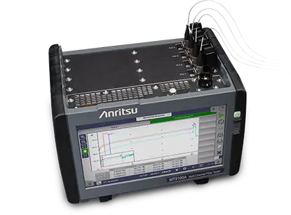
Anritsu MT9100A Multi Channel Fiber Tester – Four-Channel OTDR for Multicore Fiber
Four-channel OTDR that measures loss, reflection and inter-core crosstalk on up to four cores of a multicore fiber at once.
- Wavelength
- 1310/1550/1625 nm±25 nm
- Wavelength
- 1310 nm±25 nm; 1550/1625 nm±10 nm
- Fiber Type
- Weakly-coupled multicore fiber (up to 4cores) that can be connected to 10/125-μm SMF; 10/125-μm single mode fiber (ITU-T G.652)
- Pulse Width
- 3 ns/10 ns/20 ns/50 ns/100 ns/200 ns/500 ns/1 μs/2 μs/4 μs/10 μs/20 μs
Overview
The Anritsu MT9100A Multi Channel Fiber Tester is an OTDR built to test weakly-coupled multicore fiber (MCF). Multicore fiber is a space division multiplexing (SDM) technology. It places several independent cores in one cladding to raise the capacity of each fiber, for uses such as submarine cables and links between data centers. Signals can leak from one core into the next (inter-core crosstalk), and the level of crosstalk changes with how the cable is installed. This means it has to be checked at every stage, from R&D and manufacturing to network construction and operation.
Multi-channel OTDR method
The MT9100A has four built-in OTDRs that run in sync. One OTDR sends a probe pulse and all of them receive the light scattered back. This lets the instrument show transmission loss, reflection and inter-core crosstalk along the length of the fiber for up to four cores. The tester switches the output port internally, so all connected cores are measured in one action without changing connections or adding an external optical switch. Only one end of the fiber needs to be accessed. The multicore fiber connects to the tester through a fan-in fan-out (FIFO) device.
Analysis and functions
The instrument finds loss and reflection events automatically and makes pass/fail judgments against preset thresholds. These include far-end crosstalk and the total crosstalk each core receives from all the other cores. A realtime measurement mode checks the connection loss of every core during splicing or connector work. Other functions include an active fiber check, a connection check for each port, level offset and actual wavelength calibration to reduce crosstalk errors, and connector end face inspection to IEC 61300-3-35 with an optional fiberscope.
Operation and connectivity
The battery-powered unit has a 9-inch touch screen. Results are saved in XTA format and can be exported as CSV. Over Ethernet, the tester can be controlled remotely with a VNC-based GUI and SCPI commands, so manufacturing inspection steps can be automated.
Key Features
- Four synchronized OTDR ports for testing up to four multicore fiber cores at once
- Measures inter-core crosstalk as a distribution along the fiber distance
- Shows attenuation loss, return loss and crosstalk waveforms
- Internal port switching evaluates all connected cores in a single action without reconnecting
- Single-ended testing with no operator or instrument needed at the far end
- Automatic event detection with pass/fail judgment, including far-end crosstalk thresholds
- Total crosstalk calculation for each core from all other cores
- Two-cursor analysis of the crosstalk increase between two points or within a specific span
- Realtime measurement mode for checking connection loss of all cores during splicing
- Active fiber check suspends the measurement when communication light is detected
- Connection check of every port before measurement
- Level offset with Auto Calibration and actual wavelength calibration to reduce crosstalk errors
- Connector end face inspection to IEC 61300-3-35 with an optional USB fiberscope
- 9-inch touch screen with battery-powered portable chassis
- Remote control over Ethernet via VNC and SCPI commands
- Waveforms saved in XTA format with CSV export
Specifications
|
Wavelength
MT9100A-010, MT9100A-011
|
1310/1550/1625 nm±25 nm
25°C, pulse width: 1 μs; excluding when the battery is being charged
|
|---|---|
|
Wavelength
MT9100A-012, MT9100A-013
|
1310 nm±25 nm; 1550/1625 nm±10 nm
1310 nm: 25°C, pulse width 1 μs. 1550/1625 nm: 25°C±3°C, pulse width 1 μs/2 μs/4 μs/10 μs/20 μs, 2 hours after warm-up. Excluding when the battery is being charged
|
| Fiber Type |
Weakly-coupled multicore fiber (up to 4cores) that can be connected to 10/125-μm SMF; 10/125-μm single mode fiber (ITU-T G.652)
Connecting a weakly-coupled multicore fiber requires a compatible fan-in fan-out device
|
| Pulse Width | 3 ns/10 ns/20 ns/50 ns/100 ns/200 ns/500 ns/1 μs/2 μs/4 μs/10 μs/20 μs |
| Dynamic Range (pulse width 20 μs) |
46/46/44 dB (typical)
Values at 1310, 1550 and 1625 nm. 25°C, SNR: 1, distance range: 100 km, average time: 180 seconds; excluding when the battery is being charged
|
| Dynamic Range (pulse width 100 ns) |
25/25/23 dB (typical)
Values at 1310, 1550 and 1625 nm. 25°C, SNR: 1, distance range: 100 km, average time: 180 seconds
|
| Dead Zone (Fresnel) |
≤1.0 m
IOR = 1.500000; 25±5°C, pulse width: 3 ns, return loss: 40 dB; width at 1.5 dB below the reflected peak
|
| Dead Zone (backscatter) |
1310 nm: ≤3.8 m; 1550 nm: ≤4.3 m; 1625 nm: ≤4.8 m
IOR = 1.500000; 25°C, pulse width: 10 ns, return loss: 55 dB, deviation: ±0.5 dB
|
| IOR Setting | 1.300000 to 1.700000 (in steps of 0.000001) |
| Distance Indication Unit | km, m, kft, ft, mi |
| Number of Sampling Points | 30,001 points max. |
| Sampling Resolution | 0.05/0.1/0.2/0.5/1/2/5/10/20/40 m |
| Loss Measurement Accuracy (Linearity) | ±0.05 dB/dB or ±0.1 dB (whichever is larger) |
| Return Loss Measurement Accuracy | ±2 dB |
| Distance Measurement Accuracy |
±1 m ±3 × measurement distance × 10^-5 ± cursor resolution
Excluding the uncertainty due to the fiber refractive index
|
| Distance Range |
0.5/1/2.5/5/10/25/50/100/200/300 km
IOR = 1.500000
|
| Realtime Sweep Time |
0.2 seconds or less
Only with "Individual Setting" measurement mode, distance range 50 km, sampling mode Standard, one measurement port selected
|
| Event Detection/Analysis Function | Automatic event detection condition settings: Connection loss (reflective/non-reflective), return loss, fiber far-end; Pass/fail judgment settings: Connection loss (non-reflective: splice), connection loss (reflective: connector/mechanical splice), return loss, transmission loss (dB/km), total loss, total return loss |
| OTDR Waveform Format | XTA or CSV |
| Loss Analysis Mode | Connection loss (LSA), point-to-point loss, point-to-point LSA, transmission loss 2PA, dB/km LSA, point-to-point loss, dB/km, total return loss |
| Average Time | 5, 10, 15, 30 seconds; 1, 2, 3, 5, 10 minutes |
| Laser Safety |
Compliant with IEC 60825-1:2014 Class 1; 21CFR1040.10 and 1040.11
Excluding compliance with IEC 60825-1 stated in Laser Notice No. 56 (issued on May 8, 2019)
|
| Crosstalk Dynamic Range |
≥84/84/81 dB
Standard; values at 1310, 1550 and 1625 nm. 25°C, pulse width: 20 μs, SNR = 1, distance range: 100 km, average time: 180 seconds, unidirectional XT
|
|---|---|
| Repeatability of Crosstalk Measurement |
≤0.33 dB
Standard deviation, 25°C, pulse width: 1 μs/20 μs, wavelength: 1550/1625 nm, unidirectional XT, Anritsu 60 km 4-core multicore fiber, adjacent cores only
|
| Positional Deviation Between Ports | ≤6 m |
| Display |
WVGA resolution (800 × 480 pixels), 9 inch
Touch screen
|
|---|---|
| Supported Languages | English and Japanese |
| OTDR Ports |
4
Port 1 is on the touch-screen side and Port 4 is the last port
|
|---|---|
| USB Interface | 2 ports (USB 2.0 Type A); 1 port (USB 2.0 Type Mini-B) |
| Ethernet Interface |
Ethernet 10M/100M/1000M, RJ45 connector: 1 port
For remote control
|
| Storage Capacity | 7 Gbytes of built-in memory |
|---|---|
| Battery | Dedicated 10.80 V rechargeable smart Li-ion battery 18440 mAh |
| Continuous Operating Time |
6 hours (typical)
Telcordia GR-196-CORE Issue2, September 2010, 25°C, battery fully charged
|
| Charging Time | 9 hours (at 25°C, typical) |
| AC Adapter Input | 100 VAC to 240 VAC, 50 Hz/60 Hz |
| AC Adapter Output | Rated 18 or 19 VDC, 13.2 A (maximum) |
| Power Consumption | 250 W or less |
| DC Input | 18 Vdc |
| Dimensions |
257.5±4 (W) × 163±4 (H) × 185.3±4 (D) mm or less
Not including protrusions
|
|---|---|
| Mass |
≤ 5.9 kg
Including the battery
|
| Operating Temperature and Humidity | Temperature: 5°C to +45°C, Humidity: ≤85% RH (no condensation) |
|---|---|
| Charging Temperature and Humidity | Temperature: 5°C to +40°C, Humidity: ≤85% RH (no condensation) |
| Storage Temperature and Humidity |
Temperature: –30°C to +60°C, Humidity: ≤90% RH (no condensation)
Not including the battery and AC adapter
|
| Storage Temperature and Humidity (with battery and AC adapter) |
–20°C to +50°C, Humidity: ≤90% RH (no condensation)
Including the battery and AC adapter
|
| CE EMC | 2014/30/EU, EN61326-1, EN61000-3-2 |
|---|---|
| CE LVD | 2014/35/EU, EN61010-1 |
| CE RoHS | 2011/65/EU, (EU) 2015/863, EN IEC 63000: 2018 |
| UKCA EMC | S.I. 2016 No.1091, EN 61326-1, EN61000-3-2 |
| UKCA LVD | S.I. 2016 No.1101, EN 61010-1 |
| UKCA RoHS | S.I. 2012 No.3032, EN IEC 63000: 2018 |
Applications
- Multicore fiber research and development
- Field testing of multicore fiber and multicore fiber cables
- Multicore fiber and cable manufacturing and inspection
- Connection quality checks of fusion-spliced or connectorized multicore fiber
- Submarine optical cable evaluation
- Data center interconnect fiber evaluation
Included
- G0418A AC Adapter (1)
- Power cord (1)
- G0423A Two LiION Batteries (1)
- Z1746A Stylus (1)
- Z2195A MT9100A Operation Manual CD (1)
- MJB-1ET250002 Attached documentation on laws and regulations (1)
Options & Accessories
| Option | Description |
|---|---|
| MT9100A-010 | Standard wavelength accuracy/UPC Polish — Port option; applied to all four ports |
| MT9100A-011 | Standard wavelength accuracy/APC Polish — Port option; applied to all four ports |
| MT9100A-012 | High wavelength accuracy/UPC Polish — Port option; applied to all four ports |
| MT9100A-013 | High wavelength accuracy/APC Polish — Port option; applied to all four ports |
| MT9100A-037 | UPC-FC Connector — For option 010/012 UPC polish; applied to all four ports |
| MT9100A-040 | UPC-SC Connector — For option 010/012 UPC polish; applied to all four ports |
| MT9100A-025 | APC-FC Connector — For option 011/013 APC polish; applied to all four ports |
| MT9100A-026 | APC-SC Connector — For option 011/013 APC polish; applied to all four ports |
| MX910000A | MCF XT Characterization — Software installed in the main unit |
| B0772A | Softcase — 5U |
| B0773A | Hard Case — 5U |
| G0306C | Video Inspection Probe — Fixed to 400x magnification (USB standard type); fiber end face check via the MT9100A utility application |
| G0382A | Autofocus Video Inspection Probe — Fixed to 400x magnification (USB auto focus type); fiber end face check via the MT9100A utility application |
| G0324A | Battery Charger — Must not be exported to China |
| G0418A | AC Adapter |
| G0423A | Two LiION Batteries |
| Z0914A | Ferrule cleaner — 1 pc; cannot be exported to EU Member States |
| Z0915A | Replacement reel for ferrule cleaner — 6 pcs for Z0914A; cannot be exported to EU Member States |
| J0617B | Replaceable optical connector (FC-PC) — Same as MT9100A-037 |
| J0619B | Replaceable optical connector (SC) — Same as MT9100A-040 |
| J0739A | Replaceable optical connector (FC-APC) — Same as MT9100A-025 |
| J1697A | Replaceable optical connector (SC-APC) — Same as MT9100A-026 |
| MT9100A-ES210 | 2 Years Extended Warranty Service |
| MT9100A-ES310 | 3 Years Extended Warranty Service |
| MT9100A-ES510 | 5 Years Extended Warranty Service |