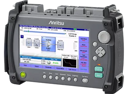
ACCESS Master MT9085B-053 1310/1550 nm SMF Handheld OTDR (Enhanced Dynamic Range)
Handheld all-in-one OTDR with 1310/1550 nm single-mode wavelengths, 42/41 dB dynamic range and an 8-inch touchscreen
- Wavelength
- 1310/1550 nm ±25 nm
- Fiber type
- Single Mode (SMF) 10/125 μm ITU-T G.652
- Pulse width
- 3, 10, 20, 30, 50, 100, 200, 500, 1000, 2000, 4000, 10000, 20000 ns
- Dynamic range
- 42/41 dB
Overview
The ACCESS Master MT9085B-053 is the general-purpose 1310/1550 nm single-mode configuration of the Enhanced Dynamic Range MT9085B model in the Anritsu MT9085 series. The series is a compact handheld all-in-one tester for optical pulse (OTDR) tests, optical loss and power measurements, and optical fiber end-face inspection, used for installation and maintenance of metro, long-haul and PON-based FTTx networks.
OTDR measurement
The OTDR measures fiber transmission loss and length and detects events such as splices, connectors, splitters and breaks. The Fiber Visualizer function displays events as schematic icons with distance, loss and reflectance Pass/Fail evaluation. Two realtime sweep modes, high-speed and high S/N, help locate fiber bends and check connections while the waveform is monitored. PON networks with up to 1 × 128 branches can be analyzed.
Power, loss and end-face inspection
A stabilized light source and an optical power meter are built in as standard through the OTDR port. Optional dedicated power meter ports support optical loss measurements with a single tester, and a visual fault locator option shows light leaking at fiber breaks. Connected to the external G0306C Video Inspection Probe, the unit inspects connector end faces with automatic Pass/Fail evaluation to IEC61300-3-35.
Operation and data handling
The 8-inch touchscreen works together with a rotary knob and dedicated hard keys, and the pressure-sensitive screen accepts input while wearing work gloves. Measurement data can be saved in original formats (.sor, .vipi), as .csv files or as PDF reports, and shared with a PC over USB, WLAN or Ethernet using external adapters.
Key Features
- 8-inch LCD touchscreen with good visibility even in direct sunlight
- Touchscreen, rotary knob and dedicated hard keys for efficient operation
- Fiber Visualizer function for simple fiber path analysis with schematic event icons
- High-speed and high S/N realtime sweep modes for fast fiber bend location
- 42/41 dB dynamic range at 1310/1550 nm (typical)
- Event dead zone ≤1 m, 0.8 m typical
- Identification of each splitter event for up to 1 × 128 branches
- Built-in stabilized light source and optical power meter as standard
- Optional visual fault locator and dedicated optical power meter ports
- Optical fiber end-face inspection with external G0306C Video Inspection Probe
- Cable Certification Test function with automatic Pass/Fail to IEC/ISO standards
- Bi-directional measurement analysis
- Live fiber detection and connection check functions
- Telcordia SR-4731 trace format support
- Scenario Manager Lite for automated test execution without a PC
- 1 GB internal memory for up to 50,000 traces
- 12-hour battery operation
- Password protection function
- Remote control via web browser GUI or remote commands
Specifications
| Wavelength |
1310/1550 nm ±25 nm
25°C, Pulse width: 1 μs
|
|---|---|
| Fiber type | Single Mode (SMF) 10/125 μm ITU-T G.652 |
| Pulse width | 3, 10, 20, 30, 50, 100, 200, 500, 1000, 2000, 4000, 10000, 20000 ns |
| Dynamic range |
42/41 dB
Typical, subtract 1 dB for guarantee. Pulse width 20 μs, distance range 100 km, averaging 180 sec., SNR = 1, 25°C
|
| Dead zone (Fresnel) |
≤1 m, 0.8 m (typ.)
IOR = 1.500000; Pulse width: 3 ns, return loss: 40 dB, 25°C
|
| Dead zone (Backscatter) |
≤5/5.5 m
IOR = 1.500000; Pulse width 3 ns, return loss 40 dB, Deviation ±0.5 dB, 25°C
|
| Laser safety |
IEC 60825-1: 2014 CLASS 1
Complies with 21CFR1040.10 and 1040.11 except for conformance with IEC 60825-1 Ed.3., as described in Laser Notice No. 56, dated May 8, 2014
|
| Distance range |
0.5, 1, 2.5, 5, 10, 25, 50, 100, 200, 300 km
Single mode
|
| Sampling points |
Up to 150,001
Either high density value is selected depending on distance range
|
| Sampling resolution | 0.05 m to 60 m |
| Distance accuracy |
±1 m ±3 × measurement distance × 10-5 ± marker resolution
Excluding IOR uncertainty
|
| Loss measurement accuracy (linearity) | ±0.05 dB/dB or ±0.1 dB (whichever is greater) |
| Reflectance accuracy |
±2 dB
Single mode; measuring the non-connected end of an approximately 25 km length fiber, Distance range: 50 km, Pulse width: 2 μs
|
| IOR setting | 1.300000 to 1.700000 (0.000001 steps) |
| Vertical scale | 0.1, 0.2, 0.5, 1.0, 2.0, 5.0, 10.0 dB/div |
| Units | km, m, kft, ft, mi |
| Real time sweep |
0.15 sec.
Resolution: Low Density
|
| OTDR trace format | Telcordia universal. SOR, issue 2 (SR-4731) |
| Operation | Auto or manual operation, displayed in table format |
|---|---|
| Pass/Fail threshold: reflective and non-reflective events |
0.01 to 9.99 dB (0.01-dB steps)
User defined
|
| Pass/Fail threshold: reflectance |
70.0 to 20.0 dB (0.1-dB steps)
User defined
|
| Pass/Fail threshold: fiber end/break |
1 to 99 dB (1-dB steps)
User defined
|
| Number of detected events | up to 99 |
| Loss modes | 2-point loss, dB/km, 2-point LSA, splice loss, ORL |
| Averaging modes | Timed (1 to 3600 s) |
| Wavelength |
Same as OTDR
CW, 25°C
|
|---|---|
| Spectral width |
≤5 nm (1310 nm), ≤10 nm (1550 nm)
CW, 25°C
|
| Wavelength accuracy |
±30 nm
1310/1550 nm; CW, 25°C
|
| Output power |
–5 ±1.5 dBm
CW, 25°C
|
| Output stability |
≤0.1 dB
CW, –10°C to 50°C (±1°C) difference between max/min. values over 1 minute, SM fiber 2 m
|
| Modes of operation |
CW, 270 Hz, 1 kHz, 2 kHz
Modulation +1.5% with 10 minute warm up
|
| Maximum input |
+10 dBm
Not available if Option 004, 005 or 007 is ordered
|
|---|---|
| Measurement range | –50 to –5 dBm |
| Accuracy |
±6.5%
CW input, –20 dBm at 1550 nm, 23°C ±2, Using Anritsu's reference single mode fiber with FC/UPC connector
|
| Setting wavelengths |
1310, 1550, 1625, 1650 nm
Options 053, 055, 057, 063
|
| Features | Store reference, loss table |
|
Measurement range
MT9085B-004
|
–50 to +23 dBm (CW, 1550 nm)
Peak power, subtract 3 dB for modulated tones
|
|---|---|
|
Measurement range
MT9085B-005
|
–43 to +30 dBm (CW, 1550 nm)
Peak power, subtract 3 dB for modulated tones
|
|
Measurement range
MT9085B-007
|
–67 to +6 dBm (CW, 1310 nm)
–60 to +3 dBm @850 nm; peak power, subtract 3 dB for modulated tones
|
| Modulation | CW, 270 Hz, 1 kHz, 2 kHz |
| Operating temperature and humidity | 0°C to +50°C, <80% (non-condensing) |
|
Central wavelength
MT9085B-002
|
650 nm±15 nm
at 25˚C
|
|---|---|
|
Optical output
MT9085B-002
|
0 ±3 dBm (CW) |
|
Optical connector
MT9085B-002
|
2.5 mm universal |
|
Laser safety
MT9085B-002
|
IEC 60825-1: 2014 CLASS 3R |
| Display | 8-inch touch screen TFT-Color LCD |
|---|---|
| Interface |
USB 2.0: Type A × 3 (memory), USB1.1: MicroB × 1 (USB mass storage)
USB power supply is 500 mA
|
| Wireless interface | WLAN via USB adapter connected to USB port |
| Data storage | Internal memory: 1 GB (up to 50,000 traces), External memory (USB): up to 32 GB |
| Languages |
English, Simplified Chinese, Traditional Chinese, French, German, Italian, Korean, Portuguese, Russian, Spanish, Swedish and Japanese
User selectable
|
| Power supply | 12 V(dc), 100 V(ac) to 240 V(ac), Allowable input voltage range: 90 V to 264 V, 50 Hz/60 Hz |
|---|---|
| Battery type |
Lithium ion
Battery Pack Z0921A, 11.1 V, 4200 mAh
|
| Battery operating time |
12 hours
Telcordia GR-196-CORE Issue 2, September 2010; typical, backlight Low, sweeping halted at 25˚C
|
| Recharge time | <5 hours (power off) |
| Power consumption | 20 W max (recharging), 4 W standard (low backlight, sweep stopped) |
| Dimensions (without protector) | 270 (W) × 165 (H) × 61 (D) mm, 10.6 × 6.5 × 2.4 inches |
|---|---|
| Mass (without protector) | 1.6 kg without battery, 1.9 kg including battery |
|
Dimensions (with protector, option 010)
MT9085B-010
|
284 (W) × 200 (H) × 77 (D) mm, 11.2 × 7.9 × 3 inches |
|
Mass (with protector, option 010)
MT9085B-010
|
2.6 kg including battery |
| Operating temperature and humidity | –10°C to +50°C, <80% (non-condensing) |
|---|---|
| Storage temperature and humidity | –20°C to +60°C, <80% (non-condensing) |
| Vibration | Conforming to MIL-T-28800E Class 3 |
| Ingress protection rating | IEC60529 IP51 |
| Shock |
MIL-T-28800E Style A (46 cm height, 8 corners, 6 faces; 14 drops in total, power off)
Bump: IEC 60068-2-27, JIS C60068-2-27
|
Applications
- Metro network installation and maintenance
- Long-haul fiber installation and maintenance
- PON-based FTTx installation and maintenance
- Mobile fronthaul and backhaul fiber testing
- Access network troubleshooting
- Fiber break location in drop cables
- Optical loss and power measurement
- Connector end-face inspection
Included
- Z1991A MT9085 Operation Manual (CD)
- W3974AE MT9085 Series Quick Guide
- Z1625A AC adapter
- Line cord
- Z0921A Battery Pack
Options & Accessories
| Option | Description |
|---|---|
| MT9085B-025 | FC-APC Connector — Key width 2.0 mm; can only connect APC-type optical fiber |
| MT9085B-026 | SC-APC Connector — Can only connect APC-type optical fiber |
| MT9085B-037 | FC Connector |
| MT9085B-038 | ST Connector |
| MT9085B-040 | SC Connector |
| MT9085B-002 | Visual Fault Locator |
| MT9085B-004 | SMF Optical Power Meter — –50 to +23 dBm |
| MT9085B-005 | SMF High Power Optical Power Meter — –43 to +30 dBm |
| MT9085B-007 | SMF/MMF Optical Power Meter — –67 to +6 dBm |
| MT9085B-010 | Protector — Front Protector B0584A cover supplied with belt as standard |
| G0306C | Video Inspection Probe — X400 magnification fixed. Displays fiber end-face condition on ACCESS Master screen and performs Pass/Fail evaluation |
| W3971AE | MT9085 Series Operation Manual — Printed |
| W3972AE | MT9085 Series SCPI Remote Control Operation Manual — Printed |
| B0745A | Softcase |
| B0582A | Soft carrying case — With shoulder strap. Can also accommodate main unit with fitted Option 010 Protector |
| B0583A | Hard transit case — Dimensions 420 (W) × 330 (H) × 148(D) mm |
| B0549 | Hard carrying case |
| B0584A | Front cover — Option 010 Protector cover only |
| Z0921A | Battery Pack — Li-ion Secondary battery, 11.1 V(dc), 4200 mAh |
| Z1632A | Battery Charger — Li-ion battery charger |
| J1295 | Car plug cord |
| J0617B | Replaceable optical connector (FC-PC) — For OTDR port, for option power meter port |
| J0618D | Replaceable optical connector (ST) — For OTDR port, for option power meter port |
| J0618F | Replaceable optical connector (HMS-10/A) — For OTDR port, for option power meter port |
| J0619B | Replaceable optical connector (SC-PC) — For OTDR port, for option power meter port |
| J0739A | Replaceable optical connector (FC-APC) — For OTDR port |
| J1697A | Replaceable optical connector (SC-APC) — For OTDR port |
| J1335A | MU/LC connector adapter — Ferrule connection adapter 2.5 mm → 1.25 mm for visual light source (Option 002 only) |
| J1530A | SC plug in converter (UPC(P)-APC(J)) — Converts main unit SC/UPC connector to SC/APC |
| J1531A | SC plug in converter (APC(P)-UPC(J)) — Converts main unit SC/APC connector to SC/UPC |
| J1532A | FC plug in converter (UPC(P)-APC(J)) — Converts main unit FC/UPC connector to FC/APC |
| J1533A | FC plug in converter (APC(P)-UPC(J)) — Converts main unit FC/APC connector to FC/UPC |
| J1534A | LC-SC Plug-in Converter (for SM, SC(P)-LC(J)) — Converts main unit SC connector to LC (SMF only) |
| J1950A | USB-Ethernet converter — For remote GUI connection |
| NETWORKS | NETWORKS PC analysis software — OTDR waveform analysis and report creation for .sor files on a Windows PC |