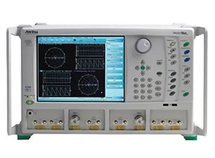
VectorStar MS4644B 40 GHz Microwave Vector Network Analyzer
VectorStar 2-port microwave vector network analyzer covering 10 MHz to 40 GHz, with an optional 70 kHz low-end frequency extension.
- Frequency range
- (Optional 70 kHz) 10 MHz to 40 GHz
- Test ports
- 2-port, K(male)
- Output default power
- +5 dBm
- Recommended calibration cycle
- 12 months
Overview
The VectorStar MS4644B is the 40 GHz model of the Anritsu MS4640B Series, Anritsu's premium vector network analyzer line for S-parameter measurements of RF, microwave and millimeter-wave devices. It covers 10 MHz to 40 GHz as standard, and Option 070 extends the low end to 70 kHz. The instrument is a 2-port VNA with K(male) test ports.
Measurement software and options
The MS4640B platform supports optional measurement capabilities, including IMDView for intermodulation distortion measurements (with single-connection switching between S-parameter and IMD measurements when combined with the internal combiner option), PulseView for pulse measurements with the IF digitizing option, DifferentialView for real-time analysis of differential devices using the dual internal source option, noise figure and differential noise figure measurements based on a cold source technique, time domain, eye diagram and Universal Fixture Extraction. A spectrum analyzer option (MS4644B-049) adds spectral-domain measurements from 70 kHz to 40 GHz, such as harmonics, spurious, distortion products and spectral occupancy.
Expansion
The MS4640B Series is the basis for 110/125/145/220 GHz broadband coaxial, banded waveguide and multiport solutions. Optoelectronic measurements are supported with the MN4765B O/E Calibration Module, and 4-port measurements with the MN469xC test sets.
EduPack Bundle
The Anritsu EduPack Bundle for universities and R&D institutions is built around a modular VectorStar MS4644B 40 GHz VNA together with a calibration kit, active measurement suite and Cadence AWR lite software, and can be combined with a Universal Test Fixture, a Spectrum Master MS276xA spectrum analyzer or a MilliBox anechoic chamber antenna measurement system.
Key Features
- Frequency coverage of 10 MHz to 40 GHz, extendable down to 70 kHz with Option 070
- 2-port configuration with K(male) test ports
- Spectrum analyzer option MS4644B-049 covering 70 kHz to 40 GHz
- Dual SPA mode for mixer, amplifier, harmonics and spurious testing
- SPA available on all ports with user-selectable SPA port
- Peak, minimum, RMS and mean detection types in classical SPA mode
- Sources and receivers independently configurable; usable as a tracking generator
- Universal Fixture Extraction (UFX) software option for test fixture de-embedding
- IMDView software with internal combiner option for S-parameter and IMD measurements in a single connection
- PulseView with 2.5 ns pulse resolution and 100 dB dynamic range
- 4-port single-ended or balanced measurements using DifferentialView analysis
- Internal trace-based eye diagram option with Time Domain and S-parameter display
- Noise figure and differential noise figure options
- Optoelectronic measurements using the MN4765B O/E Calibration Module
- 3-year warranty
Specifications
| Frequency range | (Optional 70 kHz) 10 MHz to 40 GHz |
|---|---|
| Test ports | 2-port, K(male) |
| Output default power |
+5 dBm
Standard (no options) and with Option 51, 61, or 62
|
| Recommended calibration cycle |
12 months
Residual specifications also require calibration kit calibration cycle adherence
|
| 0.07 to 0.3 MHz | 85 dB |
|---|---|
| > 0.3 to 2 MHz | 102 dB |
| > 2 to 10 MHz | 115 dB |
| > 0.01 to < 2.5 GHz | 122 dB |
| 2.5 to 40 GHz | 119 dB |
|
> 0.01 to < 2.5 GHz
Option 31
|
129 dB
With Option 31
|
|
2.5 to 40 GHz
Option 31
|
122 dB
With Option 31
|
| 0.07 to 0.3 MHz |
–75 dBm
10 Hz IF bandwidth, no averaging, –10 dBm port power, RMS
|
|---|---|
| > 0.3 to 2 MHz |
–92 dBm
10 Hz IF bandwidth, no averaging, –10 dBm port power, RMS
|
| > 2 to 10 MHz |
–105 dBm
10 Hz IF bandwidth, no averaging, –10 dBm port power, RMS
|
| > 0.01 to < 2.5 GHz |
–110 dBm
10 Hz IF bandwidth, no averaging, –10 dBm port power, RMS
|
| 2.5 to 40 GHz |
–110 dBm
10 Hz IF bandwidth, no averaging, –10 dBm port power, RMS
|
| 70 kHz to 0.01 GHz |
+10 to –25 dBm
Maximum rated power to minimum level
|
|---|---|
| > 0.01 to < 2.5 GHz |
+12 to –25 dBm
Maximum rated power is typical from 2.4 GHz to 2.7 GHz
|
| 2.5 to 20 GHz | +9 to –20 dBm |
| > 20 to 40 GHz | +9 to –25 dBm |
|
70 kHz to 0.01 GHz
Option 31
|
+12 to –25 dBm
With Option 31
|
|
> 0.01 to < 2.5 GHz
Option 31
|
+14 to –25 dBm
With Option 31
|
|
2.5 to 20 GHz
Option 31
|
+12 to –20 dBm
With Option 31
|
|
> 20 to 40 GHz
Option 31
|
+12 to –25 dBm
With Option 31
|
|
> 20 to 40 GHz
Option 61, Option 62
|
+7 to –95 dBm
Option 61 or 62; applies to Port 1
|
| Resolution | 1 Hz |
|---|---|
| Accuracy |
± 5 x 10⁻⁷ Hz/Hz
At time of calibration
|
| Stability (temperature) |
< 5 x 10⁻⁹/°C
Over 0 °C to 50 °C temperature
|
| Stability (aging) |
< 1 x 10⁻⁹/day
Aging, instrument on
|
| Directivity, > 20 to 40 GHz |
> 14 dB
Characteristic performance with Option 31, 51, 61, or 62
|
|---|---|
| Port match, > 20 to 40 GHz |
> 7 dB
Worst of source and load match
|
| Directivity, 2.5 to 5 GHz | > 20 dB |
| Directivity, > 20 to 40 GHz | > 40 dB |
|---|---|
| Source match, > 20 to 40 GHz | > 34 dB |
| Load match, > 20 to 40 GHz |
> 40 dB
Limited by residual directivity
|
| Reflection tracking, > 20 to 40 GHz | ± 0.006 dB |
| Transmission tracking, > 20 to 40 GHz | ± 0.08 dB |
| Directivity, > 20 to 40 GHz | > 46 dB |
|---|---|
| Source match, > 20 to 40 GHz | > 46 dB |
| Load match, > 20 to 40 GHz | > 46 dB |
| Reflection tracking, > 20 to 40 GHz | ± 0.14 dB |
| Transmission tracking, > 20 to 40 GHz | ± 0.07 dB |
| SSB phase noise at 10 kHz offset, > 26.5 to 40 GHz |
–76 dBc/Hz
Typical, at default power
|
|---|---|
| Harmonics (second and third) |
–20 dBc
At default power
|
Specifications are taken from the manufacturer's documentation. See the datasheet for complete and current values.
Applications
- S-parameter measurements of RF and microwave devices
- Device modeling
- R&D design validation
- Manufacturing test
- Intermodulation distortion measurements
- Pulse measurements
- Noise figure measurements
- Differential device characterization
- Mixer and frequency-translated measurements
- Time domain analysis
- Signal integrity
- Material measurements
- Antenna measurements
- On-wafer measurements
- E/O and O/E converter measurements
- University teaching and research labs
Options & Accessories
| Option | Description |
|---|---|
| MS4644B-049 | 70 kHz to 40 GHz Spectrum Analyzer option |
| Option 001 | Rack Mount |
| MS4640B-002 | Time Domain with advanced capabilities |
| MS4640B-007 | Receiver Offset with Multiple Source Control for frequency-translated measurements |
| MS4640B-021 | Universal Fixture Extraction |
| MS464xB-031 | Dual Source |
| MS464xB-032 | Internal Combiner |
| Option 036 | Extended Memory — Must be purchased with Option 35 |
| MS4640B-041 | Noise Figure |
| Option 042 | PulseView |
| MS4640B-043 | DifferentialView |
| MS4640B-044 | IMDView |
| MS4640B-046 | Fast CW |
| MS4640B-047 | Eye Diagram |
| MS4640B-048 | Differential Noise Figure |
| MS464xB-051 | Direct Access Loops |
| MS4640B-053 | External ALC leveling |
| MS464xB-061/062 | Active Measurement Suites with 2 or 4 attenuators |
| MS4640B-070 | 70 kHz Low-End Frequency Extension |
| Option 08x | Broadband/Millimeter Wave Interface |
| MN469xC | 4-port Test Sets, K and V — For 70 kHz to 70 GHz multi-port solutions |
| MN4765B | O/E Calibration Module — Optical VNA measurements; options available for 40, 70 GHz and 110 GHz, at 850, 1060, 1310, and 1550 nm wavelengths |