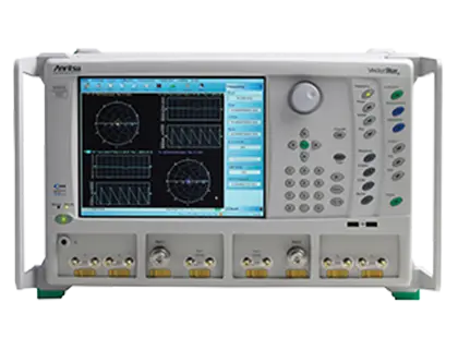
VectorStar MS4642B 20 GHz 2-Port Microwave Vector Network Analyzer
VectorStar 2-port microwave vector network analyzer covering 10 MHz to 20 GHz, extendable down to 70 kHz with Option 70.
- Frequency range
- (Optional 70 kHz) 10 MHz to 20 GHz
- Test ports
- 2-port, K(male)
- Output default power
- +5 dBm
- Recommended calibration cycle
- 12 months
Overview
The Anritsu VectorStar MS4642B is the 20 GHz model of the MS4640B Series of microwave vector network analyzers (VNAs). It is a 2-port instrument with K(male) test ports that covers 10 MHz to 20 GHz as standard, and 70 kHz to 20 GHz with Option 70 Low-End Frequency Extension.
The MS4642B is intended for S-parameter characterization of RF and microwave devices in device modeling, R&D and manufacturing environments. The MS4642B is supplied in configurations with Option 61 or 62 (Active Measurement Suite), and its system dynamic range and power range are specified for those configurations, with and without the Option 31 dual source.
Measurement Applications
Software options extend the instrument beyond S-parameters. IMDView provides real-time intermodulation distortion measurements, and with the Option 32 internal combiner the analyzer can switch between S-parameter and IMD measurements without reconnecting the device under test. PulseView supports pulsed measurements, and DifferentialView supports analysis of differential devices using the dual internal source option.
Spectrum Analysis and Noise Figure
Option 49 adds a spectrum analyzer mode covering 70 kHz to 20 GHz on the MS4642B. It is used for harmonics, spurious, distortion and spectral occupancy measurements. Noise figure (Option 41) uses a cold source technique, and Option 48 adds differential noise figure measurement.
Calibration and De-embedding
The analyzer supports 12-term SOLT, sliding load, .s1p-based and AutoCal calibrations. Universal Fixture Extraction (Option 21) provides de-embedding tools for test fixtures, and time domain analysis is available with Option 2.
Key Features
- Frequency range 10 MHz to 20 GHz, extendable to 70 kHz with Option 70
- 2-port configuration with K(male) test ports
- Spectrum analyzer option (MS4642B-049) covering 70 kHz to 20 GHz
- Dual SPA mode for mixer, amplifier, harmonics and spurious testing
- Peak, minimum, RMS and mean detection types in spectrum analyzer mode
- Sources and receivers independently configurable; usable as a tracking generator
- Universal Fixture Extraction (UFX) software option for test fixture de-embedding
- IMDView with internal combiner option for S-parameter and IMD measurements in a single connection
- PulseView with 2.5 ns pulse resolution and 100 dB dynamic range
- DifferentialView analysis of differential devices with the dual internal source option
- Internal trace-based eye diagram option with time domain and S-parameter display
- Noise figure based on a cold source technique, plus a Differential Noise Figure option
- Optoelectronic measurements using the MN4765B O/E Calibration Module
Specifications
| Frequency range |
(Optional 70 kHz) 10 MHz to 20 GHz
70 kHz low end with Option 070
|
|---|---|
| Test ports | 2-port, K(male) |
| Output default power |
+5 dBm
Option 51, 61, or 62
|
| Recommended calibration cycle |
12 months
Residual specifications also require calibration kit calibration cycle adherence
|
|
0.07 to 0.3 MHz
Option 61, Option 62
|
81 dB at Ports 1 or 2; 112 dB at b1 or b2
Option 61 or 62. Option 61 value corresponds to S21; for S12 add 2 dB
|
|---|---|
|
> 0.3 to 2 MHz
Option 61, Option 62
|
98 dB at Ports 1 or 2; 124 dB at b1 or b2
Option 61 or 62
|
|
> 2 to 10 MHz
Option 61, Option 62
|
111 dB at Ports 1 or 2; 132 dB at b1 or b2
Option 61 or 62
|
|
> 0.01 to < 2.5 GHz
Option 61, Option 62
|
114 dB at Ports 1 or 2; 135 dB at b1 or b2
Option 61 or 62
|
|
2.5 to 20 GHz
Option 61, Option 62
|
115 dB at Ports 1 or 2; 130 dB at b1 or b2
Option 61 or 62
|
|
0.07 to 0.3 MHz (with Option 31)
Option 31
|
83 dB at Ports 1 or 2; 114 dB at b1 or b2
Option 61 or 62
|
|
> 0.3 to 2 MHz (with Option 31)
Option 31
|
100 dB at Ports 1 or 2; 126 dB at b1 or b2
Option 61 or 62
|
|
> 2 to 10 MHz (with Option 31)
Option 31
|
113 dB at Ports 1 or 2; 134 dB at b1 or b2
Option 61 or 62
|
|
> 0.01 to < 2.5 GHz (with Option 31)
Option 31
|
116 dB at Ports 1 or 2; 137 dB at b1 or b2
Option 61 or 62
|
|
2.5 to 20 GHz (with Option 31)
Option 31
|
116 dB at Ports 1 or 2; 131 dB at b1 or b2
Option 61 or 62
|
|
0.07 to 0.3 MHz
Option 61, Option 62
|
–73 dBm at Ports 1 or 2; –104 dBm at bx loops
Option 61 or 62; 10 Hz IF bandwidth, –10 dBm port power. Port 1 value is 1 dB more negative on MS4642B
|
|---|---|
|
> 0.3 to 2 MHz
Option 61, Option 62
|
–90 dBm at Ports 1 or 2; –116 dBm at bx loops
Option 61 or 62
|
|
> 2 to 10 MHz
Option 61, Option 62
|
–103 dBm at Ports 1 or 2; –124 dBm at bx loops
Option 61 or 62
|
|
> 0.01 to < 2.5 GHz
Option 61, Option 62
|
–104 dBm at Ports 1 or 2; –125 dBm at bx loops
Option 61 or 62
|
|
2.5 to 20 GHz
Option 61, Option 62
|
–103 dBm at Ports 1 or 2; –118 dBm at bx loops
Option 61 or 62; table band 2.5 to 40 GHz
|
|
70 kHz to 0.01 GHz
Option 61, Option 62
|
+8 to –95 dBm
Option 61 or 62; for Option 61 applies to Port 1, for Port 2 add 1 dB to the maximum
|
|---|---|
|
> 0.01 to < 2.5 GHz
Option 61, Option 62
|
+10 to –95 dBm
Option 61 or 62
|
|
2.5 to 20 GHz
Option 61, Option 62
|
+11 to –90 dBm
Option 61 or 62
|
|
70 kHz to 0.01 GHz (with Option 31)
Option 31
|
+10 to –95 dBm |
|
> 0.01 to < 2.5 GHz (with Option 31)
Option 31
|
+12 to –95 dBm |
|
2.5 to 20 GHz (with Option 31)
Option 31
|
+12 to –90 dBm |
|
Source 1 to Port 1, 70 kHz to 0.01 GHz (Option 31 and 32)
Option 31, Option 32
|
+8 to –95 dBm
Option 61 or 62
|
|
Source 1 to Port 1, > 0.01 to < 2.5 GHz (Option 31 and 32)
Option 31, Option 32
|
+10 to –95 dBm
Option 61 or 62
|
|
Source 1 to Port 1, 2.5 to 20 GHz (Option 31 and 32)
Option 31, Option 32
|
+10 to –90 dBm
Option 61 or 62
|
|
Source 2 to Port 2, 70 kHz to 0.01 GHz (Option 31 and 32)
Option 31, Option 32
|
+6 to –95 dBm
Option 61 or 62
|
|
Source 2 to Port 2, > 0.01 to < 2.5 GHz (Option 31 and 32)
Option 31, Option 32
|
+8 to –95 dBm
Option 61 or 62
|
|
Source 2 to Port 2, 2.5 to 20 GHz (Option 31 and 32)
Option 31, Option 32
|
+9 to –90 dBm
Option 61 or 62
|
| Power accuracy, 70 kHz to 0.01 GHz |
± 1.5 dB
Measured at default power
|
|---|---|
| Power accuracy, > 0.01 to 20 GHz |
± 1.5 dB
Measured at default power; table band > 0.01 to 40 GHz
|
| Power linearity, 70 kHz to 0.01 GHz |
± 1.5 dB
Measured between default and 5 dB below default port power
|
| Power linearity, > 0.01 to 20 GHz |
± 1.0 dB
Measured between default and 5 dB below default port power
|
| Power resolution | 0.01 dB |
|
0.1 dB compression, 0.07 to 0.3 MHz
Option 61, Option 62
|
+5 dBm at Ports 1 or 2; –15 dBm at bx loops
Option 61 or 62, Port 2; 0.3 dB for < 0.3 MHz. For MS4642B Port 1 subtract 1 dB. Characteristic
|
|---|---|
|
0.1 dB compression, > 0.3 MHz to < 2.5 GHz
Option 61, Option 62
|
+12 dBm at Ports 1 or 2; –9 dBm at bx loops
Option 61 or 62, Port 2. Characteristic
|
|
0.1 dB compression, 2.5 to 5 GHz
Option 61, Option 62
|
+12 dBm at Ports 1 or 2; –4 dBm at bx loops
Option 61 or 62, Port 2. Characteristic
|
|
0.1 dB compression, > 5 to 20 GHz
Option 61, Option 62
|
+12 dBm at Ports 1 or 2; –3 dBm at bx loops
Option 61 or 62, Port 2. Characteristic
|
| Third order intercept point (IP3), 0.07 MHz to 0.3 MHz |
+20 dBm
At Port 2, nominal
|
| Third order intercept point (IP3), 0.3 MHz to 1.0 GHz |
+25 dBm
At Port 2, nominal
|
| Third order intercept point (IP3), > 1.0 GHz to 20 GHz |
+35 dBm
At Port 2, nominal
|
| 70 kHz to 500 kHz |
< 0.04 dB magnitude; < 0.4° phase
1 kHz IF bandwidth, default power, RMS
|
|---|---|
| > 500 kHz to 20 GHz |
< 0.0045 dB magnitude; < 0.05° phase
1 kHz IF bandwidth, default power, RMS
|
| 70 kHz to 0.01 GHz |
< 0.04 dB/°C magnitude; < 0.4 degree/°C phase
Ratio measurement, ports shorted. Characteristic
|
|---|---|
| > 0.01 to 20 GHz |
< 0.02 dB/°C magnitude; < 0.2 degree/°C phase
Ratio measurement, ports shorted. Characteristic
|
| Frequency resolution | 1 Hz |
|---|---|
| Frequency accuracy |
± 5 x 10⁻⁷ Hz/Hz
At time of calibration
|
| Frequency stability | < 5 x 10⁻⁹/°C over 0 °C to 50 °C; < 1 x 10⁻⁹/day aging, instrument on |
| SSB phase noise, > 0.01 to < 2.5 GHz |
–90 dBc/Hz at 1 kHz; –92 dBc/Hz at 10 kHz; –96 dBc/Hz at 100 kHz offset
Typical, at default power
|
|---|---|
| SSB phase noise, 2.5 to 5 GHz |
–93 dBc/Hz at 1 kHz; –94 dBc/Hz at 10 kHz; –95 dBc/Hz at 100 kHz offset
Typical, at default power
|
| SSB phase noise, > 10 to 20 GHz |
–81 dBc/Hz at 1 kHz; –84 dBc/Hz at 10 kHz; –84 dBc/Hz at 100 kHz offset
Typical, at default power
|
| Harmonics (second and third) |
–20 dBc
Typical from 2.5 to 2.7 GHz on MS4642B
|
| Non-harmonic spurious at > 1 kHz offsets |
–30 dBc
> 0.01 GHz; –20 dBc from 70 kHz to 0.01 GHz. Characteristic
|
| 70 kHz to 0.01 GHz |
Directivity > 10 dB; Port Match > 8 dB
Raw directivity degraded to 4 dB (typical) below 300 kHz
|
|---|---|
| > 0.01 to < 2.5 GHz |
Directivity > 9 dB; Port Match > 10 dB
Raw directivity degraded to 4 dB (typical) in a 300 MHz window below 2.5 GHz
|
| 2.5 to 5 GHz |
Directivity > 20 dB; Port Match > 10 dB
Characteristic
|
| > 5 to 20 GHz |
Directivity > 17 dB; Port Match > 9 dB
Characteristic
|
| 70 kHz to 0.01 GHz | Directivity > 38 dB; Source Match > 36 dB; Load Match > 38 dB; Reflection Tracking ± 0.02 dB; Transmission Tracking ± 0.05 dB |
|---|---|
| > 0.01 to < 2.5 GHz | Directivity > 42 dB; Source Match > 41 dB; Load Match > 42 dB; Reflection Tracking ± 0.005 dB; Transmission Tracking ± 0.03 dB |
| 2.5 to 20 GHz | Directivity > 43 dB; Source Match > 39 dB; Load Match > 43 dB; Reflection Tracking ± 0.006 dB; Transmission Tracking ± 0.07 dB |
| 70 kHz to 0.01 GHz |
Directivity > 40 dB; Source Match > 40 dB; Load Match > 43 dB; Reflection Tracking ± 0.10 dB; Transmission Tracking ± 0.10 dB
Typical performance below 2 MHz
|
|---|---|
| > 0.01 to < 2.5 GHz | Directivity > 43 dB; Source Match > 46 dB; Load Match > 43 dB; Reflection Tracking ± 0.05 dB; Transmission Tracking ± 0.03 dB |
| 2.5 to 20 GHz | Directivity > 46 dB; Source Match > 46 dB; Load Match > 46 dB; Reflection Tracking ± 0.09 dB; Transmission Tracking ± 0.03 dB |
Specifications are taken from the manufacturer's documentation. See the datasheet for complete and current values.
Applications
- S-parameter measurements of RF and microwave devices
- Device modeling
- R&D component design
- Manufacturing test
- Intermodulation distortion measurements
- Pulsed RF measurements
- Differential device characterization
- Noise figure measurements
- Harmonics and spurious measurements
- Mixer and amplifier test
- Test fixture de-embedding
- Time domain analysis
- Electro-optical and opto-electrical component measurements
- Material measurements
- Antenna measurements
Options & Accessories
| Option | Description |
|---|---|
| MS4642B-049 | 70 kHz to 20 GHz Spectrum Analyzer option |
| Option 001 | Rack Mount |
| Option 002 | Time Domain with advanced capabilities |
| Option 007 | Receiver Offset with Multiple Source Control for frequency-translated measurements |
| Option 021 | Universal Fixture Extraction |
| Option 031 | Dual Source |
| Option 032 | Internal Combiner |
| Option 036 | Extended Memory — Must be purchased with Option 35 |
| Option 041 | Noise Figure |
| Option 042 | PulseView |
| Option 043 | DifferentialView |
| Option 044 | IMDView |
| Option 046 | Fast CW |
| Option 047 | Eye Diagram |
| Option 048 | Differential Noise Figure |
| Option 053 | External ALC leveling |
| Option 05x | Direct Access Loops |
| Option 06x | Active Measurement Suites with 2 or 4 attenuators |
| Option 070 | 70 kHz Low-end Frequency Extension |
| Option 08x | Broadband/Millimeter Wave Interface |
| MN469xC | 4-port Test Sets, K and V — For 70 kHz to 70 GHz multi-port solutions |
| MN4765B | O/E Calibration Module — Optical VNA measurements; options available for 40, 70 GHz and 110 GHz, at 850, 1060, 1310, and 1550 nm wavelengths |