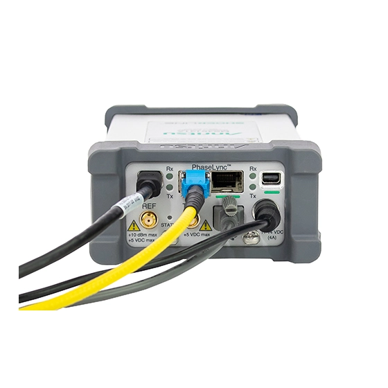
ShockLine ME7868A-020-25 Modular 2-Port PhaseLync Vector Network Analyzer, 1 MHz to 20 GHz, 25 Meter System
Distributed modular 2-port VNA covering 1 MHz to 20 GHz, with two PhaseLync-synchronized MS46131A ports up to 25 meters apart.
- Operating frequency
- 1 MHz to 20 GHz
- Frequency resolution
- 1 Hz
- Frequency accuracy
- ± 1.0 ppm
- Frequency stability
- ± 1.0 ppm from -10 °C to +55 °C
Overview
The ShockLine ME7868A-020-25 is the 20 GHz, 25 meter configuration of the Anritsu ME7868A modular 2-port vector network analyzer. The system is made up of two ShockLine MS46131A 1-port VNAs synchronized with PhaseLync technology. It covers 1 MHz to 20 GHz and makes S-parameter and time domain measurements.
The two MS46131A VNAs act as the test ports and set the performance of the instrument, because they supply both the source and the measurement capability of the 2-port VNA. The MS46131A uses ShockLine VNA on-chip technology, which simplifies the internal VNA architecture at high frequencies, cuts size and cost, and improves accuracy and measurement repeatability.
PhaseLync phase-synchronizes the two MS46131A units so the system can measure complex 2-port S-parameters on passive RF and microwave devices. The ports connect directly to the device under test, so long test cables to a benchtop VNA are not needed. This reduces insertion loss and improves measurement stability. The 25 meter configuration ships with a PhaseLync cable assembly and an accessory kit with multi-function extenders, so the setup can be controlled and communicated with from either end.
Software and control
An external PC controls both MS46131A VNAs over USB. The common ShockLine software provides a graphical interface for debugging and manual testing, plus a command syntax shared across the ShockLine VNA family for remote programming. Port configuration can be changed between sessions (single 1-port, dual 1-ports or single 2-port). The units have no on-board data storage, which suits secure applications.
Key Features
- 2-port VNA from 1 MHz to 20 GHz in a 25 meter distributed configuration
- Two MS46131A 1-port VNAs phase-synchronized with PhaseLync technology
- Small, lightweight ports connect directly to the DUT, so long cable runs are not needed
- PC control uses the processing power of an external computer
- No on-board data storage, for use in secure applications
- Common ShockLine control software for debug and test
- VNA port count configurable as single 1-port, dual 1-ports or single 2-port
- Optional low-pass time domain with time gating (MS46131A-002)
- Ruggedized K(m) test ports
Specifications
| Operating frequency |
1 MHz to 20 GHz
Applies to all PhaseLync cable lengths
|
|---|---|
| Frequency resolution | 1 Hz |
| Frequency accuracy |
± 1.0 ppm
At time of calibration
|
| Frequency stability |
± 1.0 ppm from -10 °C to +55 °C
Typical
|
| Aging |
± 1.0 ppm/year
Typical
|
| 1 MHz to 5 GHz |
97 dB (110 typical)
High source power minus RMS noise floor at 10 Hz IF bandwidth, High isolation mode
|
|---|---|
| > 5 GHz to 8.5 GHz |
97 dB (105 typical)
Satellite unit SDR degrades to 89 (105 typical) from > 5 GHz to 7 GHz; dynamic range may be degraded in a narrow range near 8 GHz in -020 models due to receiver residuals
|
| > 8.5 GHz to 20 GHz | 98 dB (110 typical) |
| 1-port, 1 MHz to 6 GHz |
Magnitude 0.009 dB (0.003 typical); Phase 0.12 deg (0.03 typical)
MS46131A-020; 100 Hz IF bandwidth, High power level, RMS
|
|---|---|
| 1-port, > 6 GHz to 8 GHz |
Magnitude 0.022 dB (0.01 typical); Phase 0.15 deg (0.08 typical)
MS46131A-020
|
| 1-port, > 8 GHz to 20 GHz |
Magnitude 0.006 dB (0.001 typical); Phase 0.1 deg (0.02 typical)
MS46131A-020; table row reads > 8 GHz to 40 GHz
|
| 2-port, 1 MHz to 4 GHz |
Magnitude 0.007 dB (0.0015 typical); Phase 0.21 deg (0.02 typical)
100 Hz IF bandwidth, High power level, RMS exclusive of drift, High Isolation Mode off
|
| 2-port, > 4 GHz to 8 GHz | Magnitude 0.011 dB (0.003 typical); Phase 0.41 deg (0.08 typical) |
| 2-port, > 8 GHz to 20 GHz | Magnitude 0.006 dB (0.0015 typical); Phase 0.41 deg (0.08 typical) |
| Receiver compression level |
+ 5 dBm
1 MHz to 43.5 GHz, all configurations; 0.1 dB compression; typical
|
|---|---|
| Output power, High (default) |
0 dBm ±2dB
Typical
|
| Output power, Low |
– 20 dBm ±2dB
Typical
|
| Output power, Off |
-50 dBm
Typical
|
| Damage input levels | +23 dBm maximum, ±50 VDC maximum |
| 1-port, 1 MHz to 43.5 GHz |
0.02 dB/ºC magnitude; 0.3 deg/ºC phase
Typical
|
|---|---|
| 2-port, 1 MHz to 8 GHz |
0.015 dB/ºC magnitude; 0.3 deg/ºC phase
Typical; electrically short thru, 15 m PhaseLync interconnect, values approximately scale with interconnect length
|
| 2-port, > 8 GHz to 20 GHz |
0.015 dB/ºC magnitude; 0.5 deg/ºC phase
Typical
|
| 1 MHz to 6 GHz |
Directivity > 6 dB; Port match > 6 dB
Typical; user and system correction off
|
|---|---|
| > 6 GHz to 8 GHz |
Directivity > 5 dB; Port match > 6 dB
Typical
|
| > 8 GHz to 20 GHz |
Directivity > 10 dB; Port match > 10 dB
Typical; table row reads > 8 GHz to 43.5 GHz
|
| 1 MHz to 10 GHz |
Directivity 42 dB; Source match 33 dB; Load match 41 dB; Reflection tracking ± 0.15 dB; Transmission tracking ±0.06 dB
Load match and tracking are characteristic performance
|
|---|---|
| > 10 GHz to 20 GHz |
Directivity 36 dB; Source match 26 dB; Load match 35 dB; Reflection tracking ± 0.15 dB; Transmission tracking ±0.06 dB
Load match and tracking are characteristic performance
|
| 1 MHz to 1 GHz | Directivity 42 dB; Source match 33 dB; Load match 41 dB; Reflection tracking ± 0.15 dB; Transmission tracking ±0.1 dB |
|---|---|
| > 1 GHz to 10 GHz | Directivity 37 dB; Source match 33 dB; Load match 41 dB; Reflection tracking ± 0.15 dB; Transmission tracking ±0.1 dB |
| > 10 GHz to 18 GHz | Directivity 37 dB; Source match 33 dB; Load match 35 dB; Reflection tracking ± 0.15 dB; Transmission tracking ±0.1 dB |
| > 18 GHz to 20 GHz | Directivity 37 dB; Source match 33 dB; Load match 35 dB; Reflection tracking ± 0.20 dB; Transmission tracking ±0.15 dB |
| Measurement speed, 1-port calibrated |
180 µs/point
Typical; 300 kHz IFBW, 1601 points; depends on external computer
|
|---|---|
| Measurement speed, 2-port calibrated |
250 µs/point
Typical; phase compensation ON, IF Gain ranging OFF
|
| 2-port measurements | S11, S21, S22, S12, and any user-defined combination of a1, a2, b1, b2, 1 |
|---|---|
| Domains | Frequency Domain, Time (Distance) Domain (Option 002) |
| Frequency sweep types | Linear, Log, CW, or Segmented |
| Maximum data points | 2 to 16,001 points |
| IF bandwidth | 10, 20, 50, 70, 100, 200, 300, 500, 700 Hz; 1, 2, 3, 5, 7, 10, 20, 30, 50, 70, 100, 200, 300 kHz |
| Averaging | Point-by-point, maximum 200; sweep-by-sweep, maximum 4096 |
| Channels and traces | 16 channels, each with up to 16 traces |
| Markers | 12 markers + 1 reference marker |
| Calibration methods | SOLT, SSLT, SSST, SOLR, LRL / LRM, TRL / TRM, SmartCal, AutoCal |
| Test port | Ruggedized K(m) |
|---|---|
| 10 MHz In connector |
SMA(f)
Signal +0 dBm, typical; 50Ω, nominal; auto-sensing
|
| External trigger connector |
SMA(f)
Input on Base MS46131A, output on Satellite MS46131A
|
| Trigger voltage input |
0 to 3.3 V input (5 V tolerant)
High impedance (> 100 k Ω); 50 ns minimum pulse width
|
| Trigger voltage output |
0 to 3.3 V (HCMOS logic)
12 mA maximum drive current
|
| USB |
One USB 2.0 (or higher) type A port per MS46131A used
On the external PC
|
| CPU | Intel® Core™ i5-6300U Processor |
|---|---|
| RAM | 4 GB |
| Disk | 120 GB |
| Operating system | Windows® 7,8, 8.1, or 10; 32 or 64 bit operating systems |
| Environmental class | MIL-PRF-28800F Class 2 |
|---|---|
| Operating temperature range | -10 ºC to 55 ºC |
| Storage temperature range | –51 ºC to 71 ºC |
| Maximum relative humidity | 95 % RH at 30 ºC, non-condensing |
| Altitude | 4600 meters, operating and non-operating |
| Recommended calibration cycle | 12 months |
|---|---|
| Warranty |
1 year from the date of shipment (standard warranty)
MS46131A and built-in options
|
Specifications are taken from the manufacturer's documentation. See the datasheet for complete and current values.
Applications
- Long distance S-parameter measurements
- Long cable insertion loss testing
- Antenna testing
- Over the Air (OTA) applications
- Chamber installations
- Large vehicle RF shielding and propagation testing
- System calibration
- Path-loss characterization
- General S-parameter and time domain measurements
- Secure area applications
Included
- Two MS46131A Modular 1-Port VNAs, each with frequency option 020 and Option 012 PhaseLync
- One 2000-2025-R (25 meter) PhaseLync Cable Assembly
- One 2000-2007-R PhaseLync Accessory Kit
- Two MN25131A Multifunction Extenders
- USB Monitor
- USB Keyboard/Mouse
- Two USB Headsets
- Extender Connection Cables
Options & Accessories
| Option | Description |
|---|---|
| MS46131A-002 | Time Domain with Time Gating — Required on both MS46131A VNAs for the option to be enabled in the ME7868A |
| MS46131A-098 | Standard Calibration, ISO 17025 compliant, without data |
| MS46131A-099 | Premium Calibration, ISO 17025 compliant, with data |
| MN25208A | 2-port USB SmartCal Module, 300 kHz to 8.5 GHz — Connector options -001 N(f), -002 K(f), -003 3.5 mm(f) |
| MN25408A | 4-port USB SmartCal Module, 300 kHz to 8.5 GHz |
| MN25218A | 2-port USB SmartCal Module, 300 kHz to 20 GHz — Available with connector Option -002 K(f) |
| MN25418A | 4-port USB SmartCal Module, 300 kHz to 20 GHz — Available with connector Option -002 K(f) |
| 3650A | SMA/3.5 mm Calibration Kit, Without Sliding Loads, DC to 26.5 GHz, 50 Ω |
| 3652A | K Connector Calibration Kit, Without Sliding Loads, DC to 40 GHz, 50 Ω |
| TOSLK50A-20 | Precision K Male Through/Open/Short/Load Mechanical Calibration Tee, DC to 20 GHz, 50 Ω |
| TOSLKF50A-20 | Precision K Female Through/Open/Short/Load Mechanical Calibration Tee, DC to 20 GHz, 50 Ω |
| 3668-4 | K Connector Verification Kit |
| 15KK50-1.0A | Test Port Cable, Armored, Phase Stable, K(m) to K(m), 1.0 m |
| 15KKF50-1.0A | Test Port Cable, Armored, Phase Stable, K(m) to K(f), 1.0 m |
| 760-295-R | Transit Case (for ME7868A VNA system) |
| 01-201 | Torque End Wrench, 5/16 in, 0.9 N·m (8 lbf·in) — For tightening male devices, for SMA, 3.5 mm, 2.4 mm, K, and V connectors |
| 01-203 | Torque End Wrench, 13/16 in, 0.9 N·m (8 lbf·in) — For tightening ruggedized SMA, 2.4 mm, K and V test port connectors |
| 01-204 | End Wrench, 5/16 in, Universal, Circular, Open-ended — For SMA, 3.5 mm, 2.4 mm, K, and V connectors |