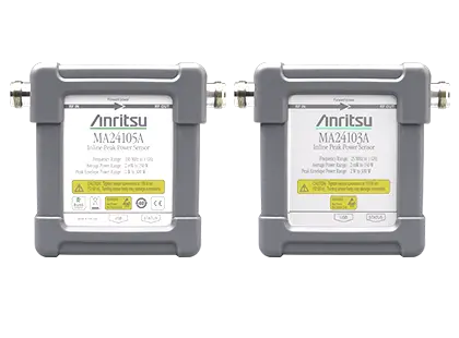
MA2410xA Inline Peak Power Sensors MA24103A and MA24105A, 25 MHz to 4 GHz
Inline peak power sensors for true-RMS average, peak, burst and reverse power measurements from 2 mW to 150 W, 25 MHz to 4 GHz.
- Frequency Range
- 25 MHz to 1 GHz
- Frequency Range
- 350 MHz to 4 GHz
- Measurement Range
- 2 mW to 150 W (+3 dBm to +51.76 dBm)
- Input Return Loss
- ≥ 29.5 dB from 25 MHz to 1 GHz
Overview
The Anritsu MA2410xA Inline Peak Power Sensors take average power measurements over 2 mW to 150 W. Two models are available: the MA24103A covers 25 MHz to 1 GHz and measures CW and multi-tone signals; the MA24105A covers 350 MHz to 4 GHz and additionally measures digitally modulated signals such as GSM/EDGE, CDMA/EV-DO, W-CDMA/HSPA+, WiMAX and TD-SCDMA.
The sensors use a dual-path architecture that provides true-RMS measurements over the entire frequency and dynamic range. The forward direction path includes a 4 MHz bandwidth channel with peak and comparator/integrator circuits, adding peak envelope power (PEP), crest factor, complementary cumulative distribution function (CCDF) and burst average power measurements. A detection circuit on the reverse direction adds reverse power, reflection coefficient, return loss and SWR measurements. A micro-controller, signal conditioning circuitry, ADC and power supply are built into the sensor, so it operates as a complete miniature power meter.
Operation with a PC
The sensor connects over USB to a PC running Microsoft Windows (including Windows 11) and is supplied with the PowerXpert application for data display, analysis and sensor control. PowerXpert provides data logging, power versus time graphs, single sensor display, real-time settings update and offset tables.
Operation with Anritsu handheld instruments
Anritsu handheld instruments fitted with high accuracy power meter software Option 19 can operate both sensors through a USB A/Micro-B cable. Compatibility with a given instrument should be confirmed against that instrument's technical data sheet.
Models in this series
| Model | Description | |
|---|---|---|
| MA24103A |
Anritsu MA24103A Inline Peak Power Sensor, True-RMS, 25 MHz to 1 GHz
USB inline peak power sensor for forward and reverse true-RMS power measurements from 2 mW to 150 W over 25 MHz to 1 GHz. |
Details → |
| MA24105A |
Anritsu MA24105A Inline Peak Power Sensor, True-RMS, 350 MHz to 4 GHz
True-RMS inline peak power sensor measuring forward and reverse power from 2 mW to 150 W over 350 MHz to 4 GHz. |
Details → |
Key Features
- Covers all major cellular and communication bands, such as WLL, GSM/EDGE, CDMA/EV-DO, WCDMA/HSDPA, WiMAX and TD-SCDMA (MA24105A)
- Forward and reverse measurements of transmitted power and reflections using a single inline sensor
- Widest dynamic range inline power sensor in its class
- True-RMS measurements to 150 W
- Low cost, plug and play device
- Suited to high crest factor signal and base station transmitter output power measurements
- High power handling > +51.7 dBm
- Compatible with most Anritsu RF and microwave handheld instruments with high accuracy power meter software Option 19
- Used with a PC via USB running Microsoft Windows and Anritsu PowerXpert software v3.49 or later
- Peak envelope power, crest factor, CCDF and burst average power measurement functions
- Reverse power, reflection coefficient, return loss and SWR measurements
Specifications
|
Frequency Range
MA24103A |
25 MHz to 1 GHz |
|---|---|
|
Frequency Range
MA24105A |
350 MHz to 4 GHz
Datasheet ordering table lists the MA24105A as 300 MHz to 4 GHz; the specification table and product page state 350 MHz |
| Measurement Range |
2 mW to 150 W (+3 dBm to +51.76 dBm)
Range 1: 2 mW to 6.31 W (+3 dBm to +38 dBm); Range 2: 6.31 W to 150 W (+38 dBm to +51.76 dBm) |
|
Input Return Loss
MA24103A |
≥ 29.5 dB from 25 MHz to 1 GHz |
|
Input Return Loss
MA24105A |
≥ 29.5 dB from 350 MHz to 3 GHz; ≥ 26.5 dB from > 3 GHz to 4 GHz |
|
Insertion Loss
MA24103A |
≤ 0.15 dB from 25 MHz to 1 GHz
Typical |
|
Insertion Loss
MA24105A |
≤ 0.15 dB from 350 MHz to 1.25 GHz; ≤ 0.20 dB from > 1.25 GHz to 4 GHz
Typical |
|
Directivity
MA24103A |
≥ 28 dB from 25 MHz to 1 GHz
Typical |
|
Directivity
MA24105A |
≥ 28 dB from 350 MHz to < 1 GHz; ≥ 30 dB from ≥ 1 GHz to ≤ 3 GHz; ≥ 28 dB from > 3 GHz to 4 GHz
Typical |
| Signal Channel Bandwidth (Forward and Reverse) | Average 100 Hz; Peak (Selectable) 4 MHz (Full), 200 kHz, 4 kHz |
| Maximum Power |
150 W average
Maximum power depends upon the system SWR and frequency of operation |
| Measurement Uncertainty |
±3.8% (Range 1 and Range 2)
Expanded uncertainty with K=2 for power measurements of a CW signal with a matched load; results referenced to the input side of the sensor |
|
Effect of Noise
MA24103A |
±510 μW (Range 1 ≥ 100 MHz), 1.2 mW (Range 1, < 100 MHz); ±6.1 mW (Range 2 ≥ 100 MHz), 17.7 mW (Range 2, < 100 MHz); ±400 μW (Reverse ≥ 100 MHz), 930 µW (Reverse, < 100 MHz)
Expanded uncertainty with K=2 after zero operation, 128 averages for 5 minutes. In high aperture time mode, noise is 50 μW and 12 mW in range 1 and range 2 respectively |
|
Effect of Noise
MA24105A |
±170 μW (Range 1); ±1.9 mW (Range 2)
Expanded uncertainty with K=2 after zero operation, 128 averages for 5 minutes. In high aperture time mode, noise is 50 μW and 12 mW in range 1 and range 2 respectively |
|
Effect of Zero Set
MA24103A |
±380 μW (Range 1 ≥ 100 MHz), 810 µW (Range 1, < 100 MHz); ±4.1 mW (Range 2 ≥ 100 MHz), 11.5 mW (Range 2, < 100 MHz); ±240 μW (Reverse ≥ 100 MHz), 820 µW (Reverse, < 100 MHz)
One-hour warm up with no operation, 128 averages for one hour, temperature within ±1 ºC |
|
Effect of Zero Set
MA24105A |
±250 μW (Range 1); ±3.0 mW (Range 2)
One-hour warm up with no operation, 128 averages for one hour, temperature within ±1 ºC |
|
Effect of Zero Drift
MA24103A |
±120 μW (Range 1 ≥ 100 MHz), 170 µW (Range 1, < 100 MHz); ±760 µW (Range 2 ≥ 100 MHz), 1.8 mW (Range 2, < 100 MHz); ±51 μW (Reverse ≥ 100 MHz), 320 µW (Reverse, < 100 MHz)
One-hour warm up with no operation, 128 averages for one hour, temperature within ±1 ºC |
|
Effect of Zero Drift
MA24105A |
±230 μW (Range 1); ±2.7 mW (Range 2)
One-hour warm up with no operation, 128 averages for one hour, temperature within ±1 ºC |
| Effect of Temperature |
±0.06 dB
0 ºC to 50 ºC |
| Effect of Digital Modulation | ±0.02 dB |
| Measurement Range, Burst Signal |
2 W to 300 W (+33 dBm to +54.77 dBm)
All measurement error effects should be RSSed before being added to the base error for overall measurement uncertainty |
|---|---|
|
Measurement Base Uncertainty
MA24103A |
Repetition Rate ≥10/s, Duty Cycle ≥10%; Full Bandwidth: ±(Base Average Power Uncertainty +7% +400 mW); 4 kHz and 200 kHz Bandwidth: ±(Base Average Power Uncertainty +3% +400 mW)
≥ 100 MHz: Pulse Power > +34 dBm, < 100 MHz: Pulse Power > +37 dBm; Pulse Width > 1 µs (Full BW), > 5 µs (200 kHz BW), > 200 µs (4 kHz BW) |
|
Measurement Base Uncertainty
MA24105A |
Repetition Rate ≥10/s, Duty Cycle ≥10%; Full Bandwidth: ±(Base Average Power Uncertainty +7% +400 mW); 4 kHz and 200 kHz Bandwidth: ±(Base Average Power Uncertainty +3% +200 mW)
Pulse Power > +34 dBm; Pulse Width > 1 µs (Full BW), > 5 µs (200 kHz BW), > 200 µs (4 kHz BW) |
| Effect of Low Repetition Rate |
±1.6% ±150 mW
≤ 10/s |
| Effect of Low Duty Cycle |
±100 mW
0.1% to 10% |
| Effect of Short Burst Width | ±5% (500 ns to 1 μs); ±10% (200 ns to < 500 ns) |
| Effect of Temperature on Peak Circuit |
±6%
0 ºC to 50 ºC |
| Measurement Range | 2 mW to 150 W (+3 dBm to +51.76 dBm) |
|---|---|
| Maximum Power |
150 W average
Maximum power depends upon the system SWR and frequency of operation |
| Measurement Uncertainty |
±(Base Average Power Uncertainty)
Expanded uncertainty with K=2 for a CW signal with a matched load; results referenced to the input side of the sensor |
|
Spread-spectrum Measurement Uncertainty
MA24103A |
N/A |
|
Spread-spectrum Measurement Uncertainty
MA24105A |
±(Base Average Power Uncertainty +15% +400 mW) |
| Measurement Uncertainty |
±0.2%
MA24103A: ≥ 100 MHz Pulse Power > +38 dBm, < 100 MHz Pulse Power > +41 dBm; MA24105A: Pulse Power > +37 dBm; T > 50 μs (Full BW), T > 400 μs (200 kHz BW), T > 20 ms (4 kHz BW) |
|---|---|
| Threshold Range |
2 mW to 300 mW (+3 dBm to +54.77 dBm)
As printed in the datasheet |
|
Accuracy of Threshold
MA24103A |
≥ 100 MHz ±(Base Average Power Uncertainty +5% +1 W), < 100 MHz ±(Base Average Power Uncertainty at +5% +2W) |
|
Accuracy of Threshold
MA24105A |
±(Base Average Power Uncertainty at +5% +500 mW) |
| Measurement Uncertainty (User Mode) | Same as Base Average Power Uncertainty except Zero Set, Zero Drift and Noise are divided by duty cycle (t/T) |
|---|---|
| Measurement Uncertainty (Auto Mode) |
±(Base Average Power Uncertainty except Zero Set, Zero Drift and Noise are divided by duty cycle (t/T) ±2%)
MA24103A: ≥ 100 MHz Average Power > +33 dBm, < 100 MHz > +36 dBm, Pulse width > 10 μs (Full BW), > 40 μs (200 kHz BW), > 3 ms (4 kHz BW); MA24105A: Average Power > +33 dBm, Pulse width > 5 μs (Full BW), > 40 μs (200 kHz BW), > 2 ms (4 kHz BW) |
| Reflection Measurement Uncertainty | ±(Base Average Power Uncertainty + Reverse Power Measurement Uncertainty) |
|---|---|
| Crest Factor Uncertainty | ±(Base Average Power Uncertainty + Forward Peak Power Measurement Uncertainty) |
| Measurement Resolution | 0.01 dB (Forward/Reverse True-RMS Average Power, Peak Power, Crest Factor, Burst Average Power); 0.01% (CCDF) |
|---|---|
| Offset Range | 100 dB (Forward/Reverse True-RMS Average Power, Peak Power, Crest Factor, Burst Average Power); 100% (CCDF) |
| Averaging Range |
1 to 512
All measurement types |
| Measurement Speed |
1.7 /s (Average Power); 2.5 /s (Peak Power); 1.4 /s (Crest Factor); 0.7 /s (Burst Average Power); 1.6 /s (CCDF)
Typical; rate at which the measurement or calculation is updated in a data log |
| RF Connectors | N (F) |
|---|---|
| USB | 180 mA typical at 5 V |
| Size (H x W x D) |
108 mm x 97 mm x 36 mm
Excluding N connectors |
| Weight | 535 g (1.18 lb) |
| Warm-Up Time |
20 minutes
Sensor left in the on state |
| Calibration Cycle |
2 years
Recommended |
| Operating Temperature |
0 °C to 50 °C
Tests performed per MIL-PRF-28800F (Class 2) |
|---|---|
| Storage Temperature | -51 °C to 71 °C |
| Maximum Relative Humidity |
45% relative humidity at 55 ºC; 75% relative humidity at 40 ºC; 95% relative humidity at 30 ºC
Non-condensing |
| Mechanical Shock | 30 g half-sine, 11 ms duration |
| Vibration | Sinusoidal: 5 to 55 Hz, 3 g max; Random: 10 Hz to 500 Hz, Power Spectral Density 0.03 g²/Hz |
| European Union | EMC 2014/30/EU, EN 61326-1:2013, CISPR 11/EN 55011, IEC/EN 61000-4-2/3/4/5/6/8/11; Low Voltage Directive 2014/35/EU; Safety EN 61010-1:2010; RoHS Directive 2011/65/EU & 2015/863 |
|---|---|
| United Kingdom | EMC SI 2016/1091; BS EN 55011 & BS 61000-4-2/3/4/5/6/8/11; Consumer Protection (Safety) SI 2016/1101; BS EN 61010-1:2010; Environmental Protection SI 2012/3032; 2011/65/EU & 2015/863 |
| Australia and New Zealand | RCM AS/NZS 4417:2012 |
| South Korea | R-R-A2J-1014 |
| Canada | ICES-1(A)/NMB-1(A) |
Applications
- Avionics antennas and airport beacons, including Instrument Landing System (ILS)
- Airport navigation and surveillance equipment such as localizers, glide paths, surveillance radars and markers
- Civil aviation air traffic communication systems
- Military aviation UHF communication systems
- Railroad braking system power monitoring and predictive maintenance
- Broadcast network and LMR base station transmitter power monitoring
- Antenna reflection measurement
- Testing high power devices such as power amplifiers
- General purpose measurement of through and reflected power
- CW, LMR, Tetra, APCO/P25, cellular, tactical military radar and avionics signals
Options & Accessories
| Option | Description |
|---|---|
| MA24103A-0098 | Option 98, Standard calibration to ISO17025 and ANSI/NCSL Z540 — Applies to MA24103A |
| MA24103A-0099 | Option 99, Premium calibration to ISO17025 and ANSI/NCSL Z540 — Test report and uncertainty data included. Applies to MA24103A |
| MA24105A-0098 | Option 98, Standard calibration to ISO17025 and ANSI/NCSL Z540 — Applies to MA24105A |
| MA24105A-0099 | Option 99, Premium calibration to ISO17025 and ANSI/NCSL Z540 — Test report and uncertainty data included. Applies to MA24105A |
| 510-90 | N(m) to 7/16 DIN(f), DC to 3.3 GHz — Precision coaxial adapter |
| 510-91 | N(f) to 7/16 DIN(f), DC to 3.3 GHz — Precision coaxial adapter |
| 510-92 | N(m) to 7/16 DIN(m), DC to 3.3 GHz — Precision coaxial adapter |
| 510-93 | N(f) to 7/16 DIN(m), DC to 3.3 GHz — Precision coaxial adapter |
| 34NFNF50 | N(m) to N(m), DC to 18 GHz — Precision coaxial adapter |
| 34AN50 | GPC-7 to N(m), DC to 18 GHz — Precision coaxial adapter |
| 34ANF50 | GPC-7 to N(f), DC to 18 GHz — Precision coaxial adapter |
| 34NFK50 | N(f) to K(m), DC to 18 GHz — Precision coaxial adapter |
| 34NFKF50 | N(f) to K(f), DC to 18 GHz — Precision coaxial adapter |
| 34NK50 | N(m) to K(m), DC to 18 GHz — Precision coaxial adapter |
| 34NKF50 | N(m) to K(f), DC to 18 GHz — Precision coaxial adapter |
| 34NN50A | DC to 18 GHz, 50 Ω, N(m)-N(m) — Precision coaxial adapter |
| 1010-121-R | 40 dB, 100 W, D to 18 GHz, N(f) to N(m), Uni-directional — Attenuator, N type |
| 3-1010-122 | 20 dB, 5 W, DC to 12.4 GHz, N(m) to N(f) — Attenuator, N type |
| 3-1010-123 | 30 dB, 50 W, DC to 8.5 GHz, N(m) to N(f) — Attenuator, N type |
| 3-1010-124 | 40 dB, 100 W, DC to 8.5 GHz, N(f) to N(m), Uni-directional — Attenuator, N type |
| 42N50-20 | 20 dB, 5 W, DC to 18 GHz, N(m) to N(f) — Attenuator, N type |
| 42N50A-30 | 30 dB, 50 W, DC to 18 GHz, N(m) to N(f) — Attenuator, N type |
| 1010-127-R | 30 dB, 150 W, DC to 3 GHz, N(m) to N(f) — Attenuator, N type |
| 1010-128-R | 40 dB, 150 W, DC to 3 GHz, N(m) to N(f) — Attenuator, N type |
| 01-200 | Calibrated Torque End Wrench, GPC-7 and Type N — Accessory |
| 2000-1593-R | 3 meters USB A to Mini-B cable — Accessory |
| 2000-1594-R | 5 meters USB A to Mini-B cable — Accessory |
| 28N50-3 | DC to 8.6 GHz, 50 Ω, N male — Precision termination, used with appropriate power attenuators |
| 28N50-2 | DC to 18 GHz, 40 dB, 50 Ω, N male — Precision termination, used with appropriate power attenuators |
| 28NF50-2 | DC to 18 GHz, 40 dB, 50 Ω, N female — Precision termination, used with appropriate power attenuators |