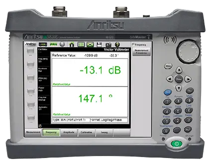
Microwave Site Master S820E Handheld Cable and Antenna Analyzer
Handheld microwave cable and antenna analyzer covering 1 MHz to 40 GHz with optional VNA and Vector Voltmeter modes.
- Frequency Range
- 1 MHz to 8 GHz, 14 GHz, 20 GHz, 30 GHz, 40 GHz
- Frequency Accuracy
- ±1.0 ppm at 23 °C
- Stability
- ±1.0 ppm from –10 °C to +55 °C
- Aging
- ±1.0 ppm/yr
Overview
The Anritsu Microwave Site Master S820E is a handheld cable and antenna analyzer with frequency options covering 1 MHz to 8, 14, 20, 30 and 40 GHz. Internally it is a four-receiver, fully reversing 2-port vector network analyzer. Vector Network Analyzer (VNA) and Vector Voltmeter (VVM) modes are available as options and are enabled with an option activation key; the hardware and calibrations they require are built into the instrument at the factory.
Cable and antenna analysis
Standard 1-port measurements include Return Loss, VSWR, Cable Loss, Smith Chart, Phase and Distance-to-Fault (Return Loss and VSWR), plus high-accuracy RF power with a USB power sensor. Standard 2-port measurements cover transmission and, with an external USB sensor, swept cable loss. External sensors allow loss measurements on long cables and waveguide assemblies whose ends are far apart; sensors can be extended with the Anritsu USB Extender 2000-1717-R and Cat 5e/Cat 6 cable. Both coaxial and waveguide measurements are supported, and patented RF interference rejection supports measurements in the presence of high RF activity. A Classic Mode user interface is provided for users of the S810D/S820D, which the S820E replaces.
VNA and VVM modes
VNA mode (option 440) provides fully reversing sweeps with simultaneous measurement of all four S-parameters, a user-configurable quad display and S2P file export in three formats for comparison with Anritsu VectorStar and ShockLine benchtop VNAs. VVM mode (option 441) provides A/B and B/A ratio measurements for use as a replacement for legacy vector voltmeters, as well as vector error corrected reflection and transmission measurements without an external CW source, couplers, bridges or splitters. A table display holds up to 12 measurements plus one reference, which is used for multi-element antenna tuning and glide slope installation work.
Fiber inspection, software and connectivity
With firmware V1.17 or later, a Video Inspection Probe (VIP) mode inspects fiber connector end faces with IEC 61300-3-35 based Pass/Fail testing using a compatible Anritsu USB probe such as the G0306A (sold separately). USB and Ethernet connectivity and SCPI remote control are standard. The free Line Sweep Tools PC software supports trace analysis and report generation, easyTest Tools provides step-by-step work instructions on the instrument, and the instrument is compatible with the Multiwave Smart Aligner Android application. A built-in help menu includes the full user guide.
Key Features
- Frequency range 1 MHz to 8, 14, 20, 30 or 40 GHz (frequency option dependent)
- Optional VNA Mode with fully reversing 4 S-parameter measurements
- Optional VVM Mode with A/B and B/A ratio capability
- VIP Mode for optical connector inspection with IEC 61300-3-35 based Pass/Fail (requires USB Video Inspection Probe G0306A, sold separately)
- 110 dB dynamic range from 20 MHz to 40 GHz (typical)
- 550 µs/data point sweep speed
- Frequency resolution of 1 Hz
- Advanced Mode and Classic Mode GUI (S810D/S820D style)
- Coaxial and waveguide measurements supported
- 1-port measurements: Return Loss, VSWR, Cable Loss, Distance-to-Fault, Smith Chart, 1-port phase
- 2-port measurements: Transmission and Swept Cable Loss
- High Accuracy Power Meter measurements with external USB power sensors
- Calibration temperature window of ±10 °C
- Full temperature calibration kits from –10 °C to +55 °C
- USB/Ethernet connectivity with full remote control capability
- 8.4 inch touchscreen with daylight/nighttime viewable modes
- Explosive Atmosphere MIL-PRF-28800F Section 4.5.6.3 compliant
- Supported by the Multiwave Smart Aligner Android application
- Standard three-year warranty (one-year warranty on battery)
Specifications
| Frequency Range |
1 MHz to 8 GHz, 14 GHz, 20 GHz, 30 GHz, 40 GHz
Frequency option dependent
|
|---|---|
| Frequency Accuracy | ±1.0 ppm at 23 °C |
| Stability |
±1.0 ppm from –10 °C to +55 °C
Typical
|
| Aging |
±1.0 ppm/yr
Typical
|
| Frequency Resolution | 1 Hz |
| IFBW |
10 Hz, 100 Hz, 1 kHz, 100 kHz
Advanced Mode only
|
| Output Power, 1 MHz to 8 GHz | +5 dBm, typical (High); –20 dBm, typical (Low) |
|---|---|
| Output Power, >8 GHz to 40 GHz | –3 dBm, typical (High); –20 dBm, typical (Low) |
| RF Immunity |
+17 dBm
Typical; +13 dBm for interfering signals landing in-band
|
| Receiver Compression, 1 MHz to 40 GHz |
+5 dBm
Port 1 or Port 2, 0.1 dB compression, typical
|
| System Impedance |
50Ω standard, 75Ω with 50Ω to 75Ω adapter
Port 1 or Port 2
|
| Measurement Speed, Reflection/Transmission |
≤550 µs/data point
RF immunity low, 100 kHz IFBW, typical
|
|---|---|
| Measurement Speed, Transmission Ext. Sensor (2-port Cable Loss) | Determined by USB sensor and may vary with model used, not specified |
| Dynamic Range, 1 MHz to 10 MHz |
≥85 dB (105 dB, typical)
High Power, 10 Hz IFBW, 10 averages, Port 1 to Port 2
|
| Dynamic Range, >10 MHz to 8 GHz |
≥100 dB (115 dB, typical)
High Power, 10 Hz IFBW, 10 averages, Port 1 to Port 2
|
| Dynamic Range, >8 GHz to 40 GHz |
≥100 dB (110 dB, typical)
High Power, 10 Hz IFBW, 10 averages; decrease specification by 5 dB between 8 GHz and 14 GHz
|
| High Level Noise, Magnitude |
±0.006 dB (±0.001 dB, typical) rms
High Power, 100 Hz IFBW, 20 MHz to 40 GHz; increased by a factor of 5.0 below 20 MHz
|
| High Level Noise, Phase |
±0.090° (±0.060°, typical)
High Power, 100 Hz IFBW, 20 MHz to 40 GHz; increased by a factor of 1.5 above 20 GHz
|
| Temperature Stability, Magnitude |
±0.02 dB/°C
Typical, 10 MHz to 40 GHz, ratio measurement, ports shorted
|
| Temperature Stability, Phase |
±0.3 degrees/°C
Typical, 10 MHz to 40 GHz, ratio measurement, ports shorted
|
| 1-Port Measurements |
Return Loss, Distance-to-Fault (DTF) Return Loss, Cable Loss, VSWR, Distance-to-Fault (DTF) VSWR, Smith Chart 50Ω/75Ω, Phase
Smith Chart and Phase in Advanced Mode only
|
|---|---|
| 2-Port Measurements |
Transmission, Transmission with External Sensor, Cable Loss (2-Port) with External Sensor
Transmission in Advanced Mode only; 2-Port Cable Loss in Classic Mode only
|
| Data Points | 130, 259, 517, 1033, 2065 |
| Sweep Averaging | 1 to 1000 |
| Smoothing Range | 0 % to 20 % |
| Return Loss Display Range |
0 dB to 1000 dB
Resolution 0.01 dB
|
| VSWR Display Range |
1 to 1000
Resolution 0.01
|
| Cable Loss Display Range |
0 dB to 500 dB
Resolution 0.01 dB
|
| DTF Horizontal Range (meters) | 0 to (Data Points – 1) x Fault Resolution, to a maximum of 1500 m (4921 ft) |
| 1-Port Phase Display Range |
–450 ° to +450 °
Resolution 0.01 °
|
| Smith Chart Impedance |
50 Ω, 75Ω
Resolution 0.01
|
| Transmission Display Range |
–1000 dB to +1000 dB
Resolution 0.01 dB
|
| Calibration | Coaxial (OSL, TOSL), Waveguide (SSL, SSLT) |
| Calibration Temperature Window | ±10 °C |
| Save Formats |
Measurement (.dat), Setups (.stp), Screen Shots (.png), Text (.txt), CSV (.csv)
Text and CSV files cannot be recalled to the instrument
|
| 1 MHz to 10 GHz |
Directivity ≥42 dB, Source Match ≥33 dB, Load Match ≥42 dB, Reflection Tracking ±0.08 dB, Transmission Tracking ±0.06 dB
Full 2-Port calibration with isolation, Default Power, 10 Hz IFBW, no averaging, 10 minute warm-up; tracking typical
|
|---|---|
| >10 GHz to 20 GHz |
Directivity ≥36 dB, Source Match ≥26 dB, Load Match ≥36 dB, Reflection Tracking ±0.04 dB, Transmission Tracking ±0.03 dB
Full 2-Port calibration with isolation; tracking typical
|
| >20 GHz to 30 GHz |
Directivity ≥32 dB, Source Match ≥22 dB, Load Match ≥32 dB, Reflection Tracking ±0.04 dB, Transmission Tracking ±0.03 dB
Full 2-Port calibration with isolation; tracking typical
|
| >30 GHz to 40 GHz |
Directivity ≥30 dB, Source Match ≥20 dB, Load Match ≥30 dB, Reflection Tracking ±0.04 dB, Transmission Tracking ±0.03 dB
Full 2-Port calibration with isolation; tracking typical; de-rate load match by approximately 8 dB with a 3670 series test port cable
|
| 1 MHz to 6 GHz |
Directivity ≥42 dB, Source Match ≥33 dB, Load Match ≥42 dB, Reflection Tracking ±0.08 dB, Transmission Tracking ±0.06 dB
Also OSLNF50A-8 or TOSLNF50A-8; tracking typical
|
|---|---|
| >6 GHz to 8 GHz |
Directivity ≥37 dB, Source Match ≥33 dB, Load Match ≥37 dB, Reflection Tracking ±0.08 dB, Transmission Tracking ±0.06 dB
Also OSLNF50A-8 or TOSLNF50A-8; tracking typical
|
|
Measurement (S-Parameter)
S820E-0440
|
S11, S21, S12, S22 |
|---|---|
|
Graph Types
S820E-0440
|
Log Magnitude, SWR, Phase, Unwrapped Phase, Real, Imaginary, Group Delay, Smith Chart (Impedance), Inverted Smith Chart (Admittance), Log Mag/2 (1-Port Cable Loss), Real Impedance, Imaginary Impedance |
|
Domain
S820E-0440
|
Frequency Domain, Distance Domain |
|
Number of Traces
S820E-0440
|
1, 2, 3, 4
Trace format Single, Dual, Tri, Quad with overlays
|
|
Data Points
S820E-0440
|
2 to 4001 (arbitrary setting) |
|
IF Bandwidth (Hz)
S820E-0440
|
10, 20, 50, 100, 200, 500, 1k, 2k, 5k, 10k, 20k, 50k, 100k |
|
Data Averaging
S820E-0440
|
Sweep-by-Sweep, 1 to 1000 |
|
Group Delay Aperture
S820E-0440
|
0.25 % to 20 %
Group delay range < 180º of phase change within the aperture
|
|
Cal Method
S820E-0440
|
Short-Open-Load-Through (SOLT), Offset-Short (SSLT)
Cal line Coax or Waveguide
|
|
Calibration Standards Coefficients
S820E-0440
|
Coax: K-Connector, N-Connector, 7/16, SMA, TNC, and four User defined; Waveguide: WG11A, WG12, WG13, WG14, WG15, WG16, WG17, WG18, WG20, WG22, and four User Defined |
|
Save Formats
S820E-0440
|
Measurement (.svna), Setup (.stp), Screen Shot (.png), S2P-Real/Imaginary (.s2p), S2P-Linear Mag/Phase (.s2p), S2P-Log Mag/Phase (.s2p), Text (.txt), CSV (.csv) |
|
Measurement Speed
S820E-0440
|
≤550 μs/pt
S11 and S21, 1001 points, 100 kHz IFBW, RF immunity low, typical; single trace display, frequency domain
|
|
RF Immunity High
S820E-0440
|
+17 dBm nominal
+13 dBm for interfering signals landing in-band
|
|
Timebase Reference
S820E-0440
|
Internal (default), External 10 MHz (Auto-sense, BNC female, Max +10 dBm) |
|
Measurements
S820E-0441
|
1-port Reflection, 2-port Transmission, Ratio A/B, Ratio B/A
Ratio measurements require external CW source; Port 1 = A, Port 2 = B
|
|---|---|
|
Measurement Format
S820E-0441
|
LogMag/Phase, LinMag/Phase, SWR, Impedance |
|
Display Format
S820E-0441
|
Single, Table (table holds up to 12 measurements plus reference) |
|
Measurement Frequency
S820E-0441
|
Set CW Frequency, 1 MHz (minimum)
Reference receiver auto-tunes approximately ±100 kHz to lock onto external CW signal in ratio measurement
|
|
IFBW
S820E-0441
|
10 Hz, 100 Hz (default), 1 kHz, 100 kHz |
|
Reference Level Input Range (A/B and B/A), 1 MHz to 40 GHz
S820E-0441
|
+5 dBm to –60 dBm (auto ranging), typical
Recommend ≤ +3 dBm for A/B or B/A ratio measurement
|
|
Ratio Accuracy, 1 MHz to 1 GHz
S820E-0441
|
≤±0.2 dB typical
Relative to stored reference, DUT loss <10 dB; reference signal level 0 to –20 dBm at input port
|
|
Ratio Accuracy, >1 GHz to 20 GHz
S820E-0441
|
≤±0.5 dB typical
Relative to stored reference, DUT loss <10 dB
|
|
Ratio Accuracy, >20 GHz to 40 GHz
S820E-0441
|
≤±1.0 dB typical
Relative to stored reference, DUT loss <10 dB
|
|
Phase Display Range
S820E-0441
|
±180°
LogMag/Phase and LinMag/Phase formats
|
|
Port 1 / Port 2 (models up to 14 GHz)
S820E-0708, S820E-0714
|
Type N, female, 50Ω, Maximum Input +23 dBm, ±50 VDC |
|---|---|
|
Port 1 / Port 2 (models > 14 GHz)
S820E-0720, S820E-0730, S820E-0740
|
Type Ruggedized K, male, 50Ω, Maximum Input +23 dBm, ±50 VDC |
| External Reference In | Type BNC female, 50Ω, 10 MHz, Maximum +10 dBm |
| External Trigger In | Type BNC female, 50Ω, 3.3 V or 5 V TTL triggers on positive edge. Maximum +5 VDC |
| Headset Jack | 3.5 mm mini-jack |
| External Power | 5.5 mm barrel connector, +11 VDC to +14 VDC, ≤4.0 A |
| USB Interface | (2) Type A, Connect USB Flash Drive, GPS Module, Power Sensor, other |
| USB Interface (PC) | 5-pin Mini-B, Connect to PC for data transfer and/or control |
| Ethernet | RJ-45, Category 5, 10/100 MB/s. Connect to PC for data transfer and/or control |
| Remote Control Programming Language |
Standard Commands for Programmable Instruments (SCPI)
Interfaces USB, LAN
|
| Display Type | High Resolution Resistive Touchscreen |
|---|---|
| Display Size | 8.4 in daylight viewable color LCD |
| Display Resolution | 800 x 600 |
| Internal Trace/Setup Memory | >2000 files, files may be traces, setups, screen shots, or any combination |
| External Trace/Setup Memory | Limited only by size of USB Flash drive |
| Battery Type | Li-Ion |
| Battery Operation | 5.0 hr, typical |
| Languages | English, French, German, Italian, Spanish, Russian, Portuguese, Japanese, Korean, Chinese |
| Environmental Standard | MIL-PRF-28800F Class 2 |
|---|---|
| Operating Temperature Range | –10 ºC to 55 ºC |
| Storage Temperature Range | –51 ºC to 71 ºC |
| Maximum Relative Humidity | 95 % RH at 30 ºC, non-condensing |
| Vibration, Sinusoidal | 5 Hz to 55 Hz |
| Vibration, Random | 10 Hz to 500 Hz |
| Half Sine Shock | 30 gn |
| Altitude | 4600 meters, operating and non-operating |
| Explosive Atmosphere | MIL-PRF-28800F Section 4.5.6.3; MIL-STD-810G, Method 511.5, Procedure 1 |
| European Union EMC | 2014/30/EU, EN 61326-1:2013, CISPR 11/EN 55011, IEC/EN 61000-4-2/3/4/5/6/8/11 |
|---|---|
| Low Voltage Directive | 2014/35/EU, Safety EN 61010-1:2010, RoHS Directive 2011/65/EU + 2015/863 |
| Australia and New Zealand | RCM AS/NZS 4417:2012 |
| South Korea | KCC-REM-A21+-0004 |
| Canada | ICES-1(A)/NMB-1(A) |
| Size | 273 mm x 199 mm x 91 mm (10.7 in x 7.8 in x 3.6 in) |
|---|---|
| Weight |
3.0 kg (6.6 lb)
Including battery
|
| Warranty | Standard three-year warranty (one-year warranty on battery) |
Specifications are taken from the manufacturer's documentation. See the datasheet for complete and current values.
Applications
- Microwave antennas
- Coaxial cables and waveguide
- RF and microwave components
- Defense and aerospace
- Cellular networks
- Public safety
- Satellite networks
- Private networks (utility, railroads)
- Education
- R&D
- Glide slope installation and verification
- Multi-array antenna system tuning
- Fiber connector inspection
Included
- 2000-1654-R Soft Carrying Case
- 2000-1371-R Ethernet Cable, 2.13 m (7 ft)
- 2000-1691-R Stylus with Coiled Tether
- 3-2000-1498 USB A/5-pin mini-B Cable, 10 ft
- 633-75 Rechargeable Li-Ion Battery, 7500 mAh
- 806-141-R Automotive Power Adapter, 12 VDC, 60 W
- 40-187-R AC-DC Adapter with power cable (country dependent)
- Certificate of Calibration and Conformance
- 71693-R Ruggedized K(f) to N(f), 2 pcs (included only with S820E-0720)
- 2000-1797-R Screen Protector Film (one factory installed, one spare)
Options & Accessories
| Option | Description |
|---|---|
| S820E-0708 | 1 MHz to 8 GHz, type N(f) ports — Frequency option (select one frequency option only) |
| S820E-0714 | 1 MHz to 14 GHz, type N(f) ports — Frequency option (select one frequency option only) |
| S820E-0720 | 1 MHz to 20 GHz, type Ruggedized K(m) ports — Compatible with 3.5 mm and SMA connectors |
| S820E-0730 | 1 MHz to 30 GHz, type Ruggedized K(m) ports — Compatible with 3.5 mm and SMA connectors |
| S820E-0740 | 1 MHz to 40 GHz, type Ruggedized K(m) ports — Compatible with 3.5 mm and SMA connectors |
| S820E-0440 | Vector Network Analyzer (VNA) — Fully reversing sweep, simultaneous measurement of 4 S-parameters with user configurable quad display; generates S2P files in three formats for import into Anritsu VectorStar and ShockLine benchtop VNAs. |
| S820E-0441 | Vector Voltmeter (VVM) — 1-port reflection and 2-port transmission measurements plus A/B or B/A ratio capability; vector error correction for absolute DUT measurements; table display of up to 12 devices + 1 reference. |
| S820E-0097 | Accredited Calibration to ISO17025 and ANSI/NCSL Z540-1 — Includes calibration certificate. |
| S820E-0098 | Standard Calibration to ISO17025 and ANSI/NCSL Z540-1 — Includes calibration certificate. |
| S820E-0099 | Premium Calibration to ISO17025 and ANSI/NCSL Z540-1 — Includes calibration certificate, test report, and uncertainty data. |
| MA24330A | Microwave CW USB Power Sensor, 10 MHz to 33 GHz, +20 dBm |
| MA24340A | Microwave CW USB Power Sensor, 10 MHz to 40 GHz, +20 dBm |
| MA24350A | Microwave CW USB Power Sensor, 10 MHz to 50 GHz, +20 dBm |
| MA24108A | Microwave USB Power Sensor, 10 MHz to 8 GHz, +20 dBm to –40 dBm |
| MA24118A | Microwave USB Power Sensor, 10 MHz to 18 GHz, +20 dBm to –40 dBm |
| MA24126A | Microwave USB Power Sensor, 10 MHz to 26 GHz, +20 dBm to –40 dBm |
| MA24208A | Microwave Universal USB Power Sensor, 10 MHz to 8 GHz, +20 dBm to –60 dBm |
| MA24218A | Microwave Universal USB Power Sensor, 10 MHz to 18 GHz, +20 dBm to –60 dBm |
| MA24105A | Inline Dual Directional High Power Sensor, 350 MHz to 4 GHz, +3 dBm to +51.76 dBm |
| MA24106A | High Accuracy RF Power Sensor, 50 MHz to 6 GHz, +23 dBm to –40 dBm |
| MA25100A | RF Power Indicator |
| SC8268 | USB Transmission Sensor, K(m), 1 MHz to 40 GHz, +10 dBm to –50 dBm — Compatible with scalar transmission measurements only. |
| 2000-1374-R | External Dual Charger for Li-Ion Batteries |
| 2000-1723-R | High Performance USB Mag-Mount GPS Antenna/Receiver |
| 67135 | Anritsu Backpack (for Handheld Instrument and PC) |
| 760-243-R | Large Transit Case with Wheels and Handle — 56 cm x 45.5 cm x 26.5 cm (22.07" x 17.92" x 10.42") |
| 760-286-R | Compact Transit Case with Wheels and Handle — 55.6 cm x 35.5 cm x 22.9 cm (21.89" x 13.98" x 9.01") |
| 2000-1900-R | Single Port 2.0 USB 100 meter Cat 5e Range Extender — With Type A power cord for USA, Japan, North America, Central America and Caribbean. |
| 2000-1717-R | USB 1.1 Passive 40 m Extender — Not compatible with sensors MA24208A, MA24218A, MA24330A, MA24340A, MA24350A; active extenders must be used with these sensors. |
| 2100-28-R | Cat 5e extension cable for use with USB Extender (22.5 m) |
| OSLN50A-8 | High Performance Type N(m), DC to 8 GHz, 50Ω calibration kit — Full temperature coaxial calibration kit, –10 °C to +55 °C |
| OSLNF50A-8 | High Performance Type N(f), DC to 8 GHz, 50Ω calibration kit — Full temperature coaxial calibration kit, –10 °C to +55 °C |
| OSLN50A-18 | High Performance Type N(m), DC to 18 GHz, 50Ω calibration kit — Full temperature coaxial calibration kit, –10 °C to +55 °C |
| OSLNF50A-18 | High Performance Type N(f), DC to 18 GHz, 50Ω calibration kit — Full temperature coaxial calibration kit, –10 °C to +55 °C |
| TOSLN50A-8 | High Performance with Through Type N(m), DC to 8 GHz, 50Ω calibration kit |
| TOSLNF50A-8 | High Performance with Through Type N(f), DC to 8 GHz, 50Ω calibration kit |
| TOSLN50A-18 | High Performance with Through Type N(m), DC to 18 GHz, 50Ω calibration kit |
| TOSLNF50A-18 | High Performance with Through Type N(f), DC to 18 GHz, 50Ω calibration kit |
| TOSLK50A-20 | High Performance with Through Type K(m), DC to 20 GHz, 50Ω calibration kit |
| TOSLKF50A-20 | High Performance with Through Type K(f), DC to 20 GHz, 50Ω calibration kit |
| TOSLK50A-40 | High Performance with Through Type K(m), DC to 40 GHz, 50Ω calibration kit |
| TOSLKF50A-40 | High Performance with Through Type K(f), DC to 40 GHz, 50Ω calibration kit |